53
SIVACON S8 Planning Principles – In-line design, plug-in
2
3
4
5
6
7
8
9
10
11
1
5.2 In-line switch-disconnectors
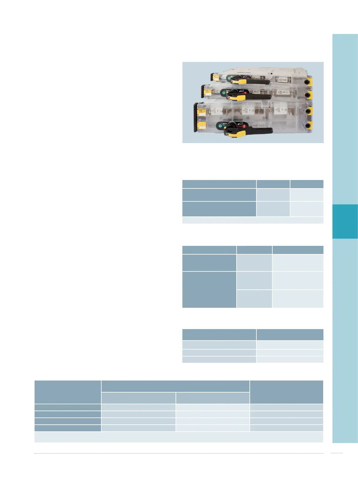
SASIL plus with fuses
Cubicles with pluggable in-line switch-disconnectors can
also be equipped with SASIL plus in-line units (Fig. 5/3)
produced by Jean Müller.
Rating data of the vertical distribution busbar SASIL
plus
The vertical distribution busbars with the phase conductors
L1, L2, L3 are arranged at the back of the cubicle. The PE, N
or PEN busbars are arranged in the cable connection com-
partment. In the case of 4-pole feeders, the N conductor is
allocated to the phase conductors L1, L2, L3 at the back of
the cubicle. The vertical distribution busbar is covered test
finger proofed (IP2X). The rated data are stated in Tab. 5/8.
Rating data of the SASIL plus cable feeders
Apart from the space requirements for additional built-in
elements (Tab. 5/9), the derating factor stated in Tab. 5/10
is to be set for determining the permissible operating
current of a fuse link. The space requirements for the cable
feeders of the different in-line units depend on the nominal
device current (Tab. 5/11).
Distribution busbar cross section
60 x 10 mm
2
80 x 10 mm
2
Rated current at 35 °C ambient
temperature
1,560 A 2,100 A
Rated short-time withstand
current I
cw
(1 sec)
1)
50 kA 50 kA
1)
Rated conditional short-circuit current I
cc
= 100 kA
Tab. 5/8: Rating data of the vertical distribution busbar SASIL plus
Fig. 5/3: Pluggable in-line switch-disconnectors SASIL plus
Built-in elements Height in mm Version
Blanking cover for
empty slots
50, 75, 150,
300
Metal
Device compartment
(mounting
plate with
compartment door)
150, 200, 300,
450, 600
Without power tapping,
usable overall device
depth 180 mm
200, 300, 450,
600
With power tapping,
usable overall device
depth 180 mm
Tab. 5/9: Additional built-in elements for SASIL plus
Tab. 5/10: Derating factors for SASIL plus fuse links
Size
Nominal device
current
Space requirements of the in-line unit (height)
1)
Rated current
1)
at 35 °C ambient temperature
3-pole 4-pole
00 160 A
50 mm 100 mm 122 A
1 250 A
75 mm 150 mm 203 A
2 400 A
150 mm 300 mm 324 A
3 630 A
150 mm 300 mm 510 A
1)
Rated current with fuse link = nominal device current
The configuration rules stated in the following are to be observed
Tab. 5/11: Rating data of the SASIL plus cable feeders
Nominal current of fuse link Derating factor F
I
n
≤ 32 A
1
32 A < I
n
≤ 160 A
0.76
160 A < I
n
≤ 630 A
0.81

 Loading...


