31
SIVACON S8 Planning Principles – Circuit-breaker design
2
3
4
5
6
7
8
9
10
11
1
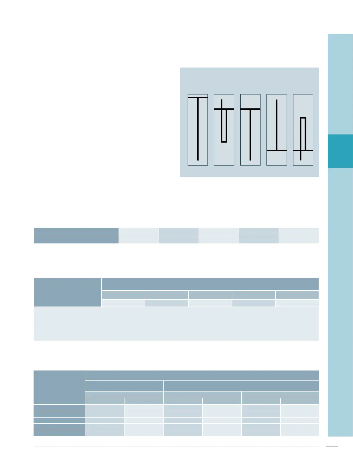
3.4 Cubicles for direct supply and
direct feeder
The different cubicle types:
1. Top busbar position, cable entry from the bottom or top
(the position of the connecting bars is identical for cable
entry from the top or bottom)
2. Rear top busbar position, cable entry from the top
3. Rear top busbar position, cable entry from the bottom
4. Rear bottom busbar position, cable entry from the top
5. Rear bottom busbar position, cable entry from the
bottom
are schematized in Fig. 3/3.
The cubicle width and maximum number of cables which
can be connected depend on the rated current (Tab. 3/13
and Tab. 3/14). The rated currents, in turn, depend on the
busbar position and cable entry (Tab. 3/15).
Fig. 3/3: Cubicle types for direct supply and direct feeder (refer to
the text for explanations)
1. 2. 3. 4. 5.
Tab. 3/13: Cubicle width for direct supply and direct feeder
Cable lug DIN 46235
(240 mm
2
, M12)
1)
Max. number of cables connectible per phase
dependent on nominal current
1,000 A 1,600 A 2,500 A 3,200 A 4,000 A
4 6 12 12 14
1)
Using 300 mm
2
cable lugs with an M12 screw is possible. However, this cable lug is not in compliance with DIN 46235, although it is
available at some manufacturers
The number of connectible cables may be restricted by the available roof/floor panel openings and/or door installations.
The position of the connection busbars is identical for front or rear connection in the cubicle.
Tab. 3/14: Cable connection for direct supply and direct feeder
Nominal current 1,000 A 1,600 A 2,500 A 3,200 A 4,000 A
Cubicle width
400 mm 400 mm 600 mm 600 mm 800 mm
Tab. 3/15: Rated currents for direct supply and direct feeder
Nominal current
Rated current at 35 °C ambient temperature
Top busbar position
Rear busbar position
Cable connection Cable entry from the bottom Cable entry from the top
Non-ventilated Ventilated Non-ventilated Ventilated Non-ventilated Ventilated
1,000 A
905 A 1,050 A 1,100 A 1,190 A 1,120 A 1,280 A
1,600 A
1,300 A 1,500 A 1,530 A 1,640 A 1,480 A 1,740 A
2,500 A
1,980 A 2,410 A 2,230 A 2,930 A 2,210 A 2,930 A
3,200 A
2,340 A 2,280 A 2,910 A 3,390 A 2,770 A 3,390 A
4,000 A
3,430 A 4,480 A 3,300 A 4,210 A 3,140 A 4,210 A

 Loading...


