37
SIVACON S8 Planning Principles – Universal mounting design
2
3
4
5
6
7
8
9
10
11
1
4.1 Fixed-mounted design with
compartment door
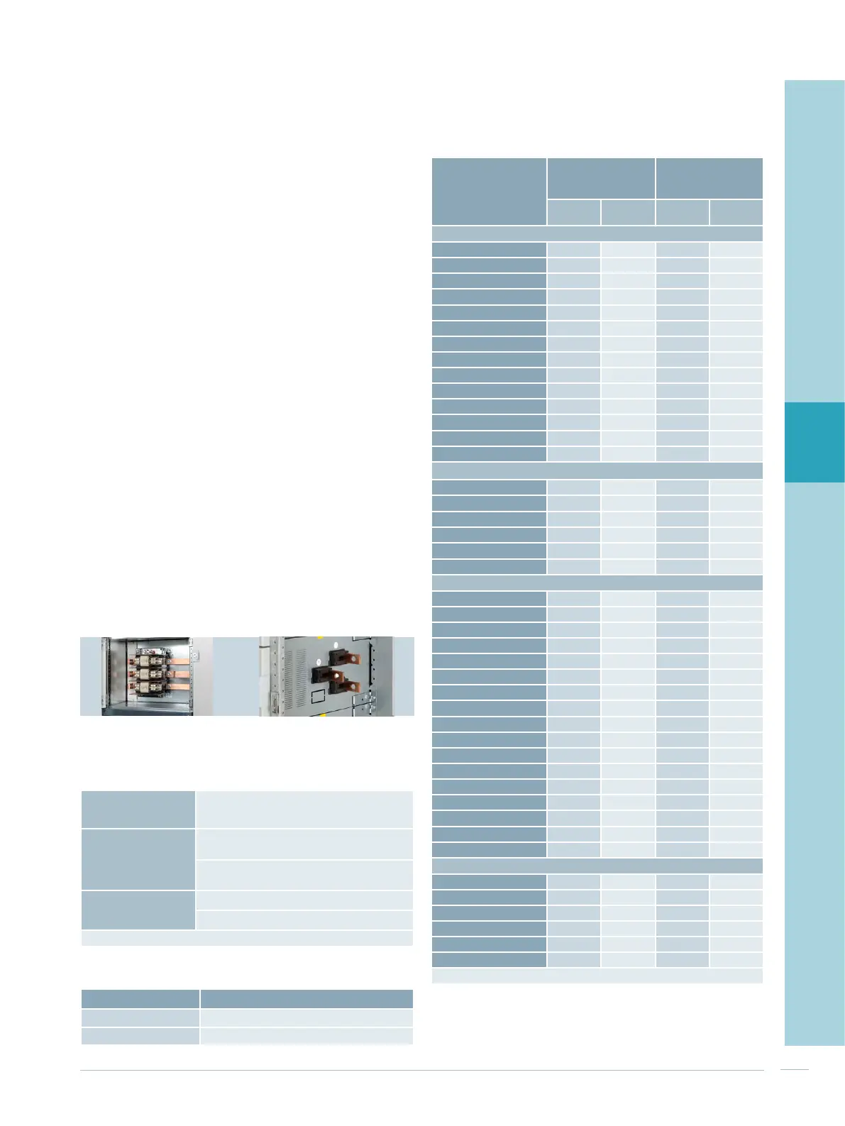
In fixed-mounted design, the switching devices are in-
stalled on mounting plates. They can be equipped with
circuit-breakers or switch-disconnectors with fuses
(Fig. 4/4; left). Tab. 4/3 gives an overview of the cubicle
characteristics in fixed-mounted design. The incoming sides
are connected to the vertical distribution busbars.
For forms 2b and 4a without current measurement, cables
are connected directly at the switching device. The maxi-
mum cross sections that can be connected are stated in the
device catalogues. For forms 3b and 4b as well as for
feeders with current measurement (transformers), the
cables are connected in the cable connection compartment
(Fig. 4/4; right). The maximum connection cross sections
are stated in Tab. 4/4.
The rating for cable feeders is stated in Tab. 4/5. The ther-
mal interaction of the feeders in the cubicle has to be and
is considered by specifying the rated diversity factor (RDF):
Permissible continuous operational current (cable feeder) =
= rated current I
nc
x RDF
For the feeders in the cubicle, the rated diversity factor RDF
= 0.8 can be applied:
• regardless of the number of feeders in the cubicle
• regardless of the mounting position in the cubicle
For cubicles with a very high packing and/or power density,
a project-specific assessment is recommended. Further
information is available from your Siemens contact.
Tab. 4/3: Cubicle characteristics for the fixed-mounted design
Application range - Incoming feeders up to 630 A
- Outgoing cable feeders up to 630 A
Form of internal
separation
- Form 2b Functional
compartment door
- Form 3b, 4a, 4b
1)
Compartment
door
Mounting designs - Fixed-mounted module in compartment
-
Empty compartment, device compartment
1)
Also form 4b type 7 in acc. with BS EN 61439-2 possible
Fig. 4/4: Equipment in fixed-mounted design (left) and connection
terminals in the cable connection compartment (right)
Tab. 4/4: Connection cross sections in fixed-mounted cubicles with
a front door
Nominal feeder current
Max. connection cross section
≤ 250 A 120 mm
2
> 250 A 240 mm
2
Tab. 4/5: Ratings for cable feeders
Type
Nominal
device
current
Module height
Rated current I
nc
at 35 °C ambient
temperature
3-pole 4-pole
Non-
ventilated
Ventilated
Fuse switch-disconnectors
1)
3NP1123 160 A
150 mm - 106 A 120 A
3NP1133 160 A
150 mm - 123 A 133 A
3NP1143 250 A
250 mm - 222 A 241 A
3NP1153 400 A
300 mm - 350 A 375 A
3NP1163 630 A
350 mm - 480 A 530 A
3NP4010 160 A
150 mm - 84 A 96 A
3NP4070 160 A
150 mm - 130 A 142 A
3NP4270 250 A
250 mm - 248 A 250 A
3NP4370 400 A
300 mm - 355 A 370 A
3NP4470 630 A
350 mm - 480 A 515 A
3NP5060
160 A
150 mm - 130 A 142 A
3NP5260 250 A
250 mm - 248 A 250 A
3NP5360 400 A
300 mm - 355 A 370 A
3NP5460
630 A
350 mm - 480 A 515 A
Switch-disconnectors with fuses
1)
3KL50 63 A
150 mm 250 mm 61 A 63 A
3KL52 125 A
250 mm 250 mm 120 A 125 A
3KL53 160 A
250 mm 250 mm 136 A 143 A
3KL55 250 A
300 mm 350 mm 250 A 250 A
3KL57 400 A
300 mm 350 mm 345 A 355 A
3KL61 630 A
450 mm 500 mm 535 A 555 A
Circuit-breakers
3RV2.1 16 A
150 mm - 12.7 A 14.1 A
3RV2.2 40 A
150 mm - 27 A 31.5 A
3RV2.3 52 A
150 mm - 39 A 40.5 A
3RV1.4 100 A
150 mm - 71 A 79 A
3VL1 160 A
150 mm 200 mm 121 A 151 A
3VL2 160 A
150 mm 200 mm 130 A 158 A
3VL3 250 A
200 mm 250 mm 248 A 250 A
3VL4 400 A
250 mm 300 mm 400 A 400 A
3VL5 630 A
250 mm 350 mm 525 A 565 A
3VA10 100 A
150 mm 200 mm 72 A 85 A
3VA11 160 A
150 mm 200 mm 112 A 125 A
3VA12 250 A
150 mm 200 mm 232 A 246 A
3VA20 100 A
150 mm 200 mm 100 A 100 A
3VA21 160 A
150 mm 200 mm 160 A 160 A
3VA22 250 A
150 mm 200 mm 201 A 226 A
3VA23 400 A
200 mm 250 mm 350 A 400 A
3VA24 630 A
200 mm 250 mm 410 A 495 A
Device compartments (usable overall depth 310 mm)
150 mm
200 mm
300 mm
400 mm
500 mm
600 mm
1)
Rated current with fuse link = nominal device current

 Loading...


