36
SIVACON S8 Planning Principles – Universal mounting design
connection compartment. In the case of 4-pole feeders, the
N conductor is allocated to the phase conductors L1, L2, L3
at the back of the cubicle. Ratings are stated in Tab. 4/2.
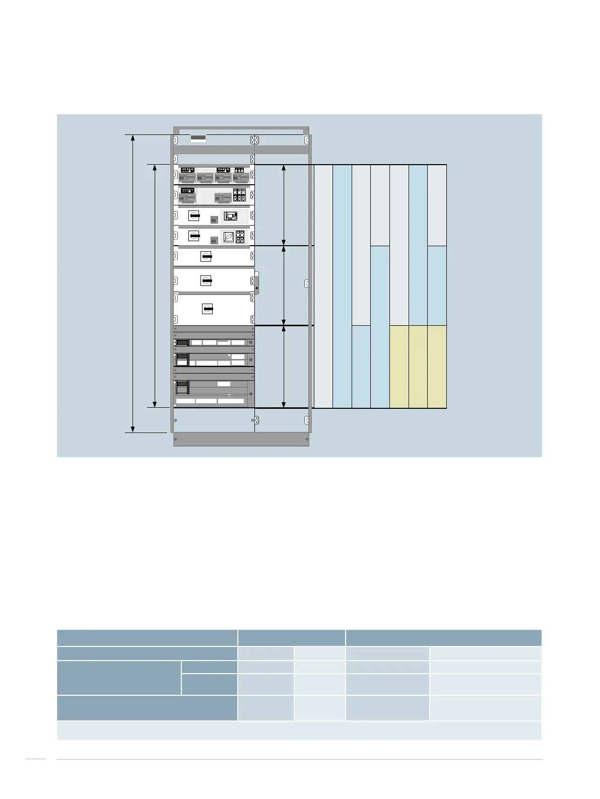
Combination of mounting designs
The different mounting designs can be combined in a
cubicle as shown in Fig. 4/3.
Vertical distribution busbar
The vertical distribution busbars with the phase conductors
L1, L2, L3 are arranged on the left at the back of the cubi-
cle. The PE, N or PEN busbars are arranged in the cable
Distribution busbar Profile bar Flat copper
1)
Cross section
400 mm
2
650 mm
2
1 x (40 mm x 10 mm) 2 x (40 mm x 10 mm)
Rated current at 35 °C ambient
temperature
Ventilated
905 A 1,100 A 865 A 1,120 A
Non-
ventilated
830 A 1,000 A 820 A 1,000 A
Rated short-time withstand
current I
cw
(1 sec)
2)
65 kA 65 kA 65 kA 65 kA
1)
Top main busbar position
2)
Rated conditional short-circuit current I
cc
= 150 kA
Tab. 4/2: Ratings of the vertical distribution busbar
Fig. 4/3: Combination options for universal mounting design
SIEMENS
SIVACON
A
2,200 / 2,000 mm
Withdrawable unit design
600 mm
1,800 / 1,600* mm
600 mm 600 / 400 * mm
Withdrawable
unit design
Withdrawable
unit design
Withdrawable unit design
Withdrawable unit design
Fixed-mounted design
Fixed-mounted
design
Fixed-mounted design
Fixed-mounted design
Fixed-mounted design
In-line design, plugged
In-line design, plugged
In-line design, plugged
* Frame height 2,000 mm

 Loading...


