18
SIVACON S8 Planning Principles – SIVACON S8 – System overview
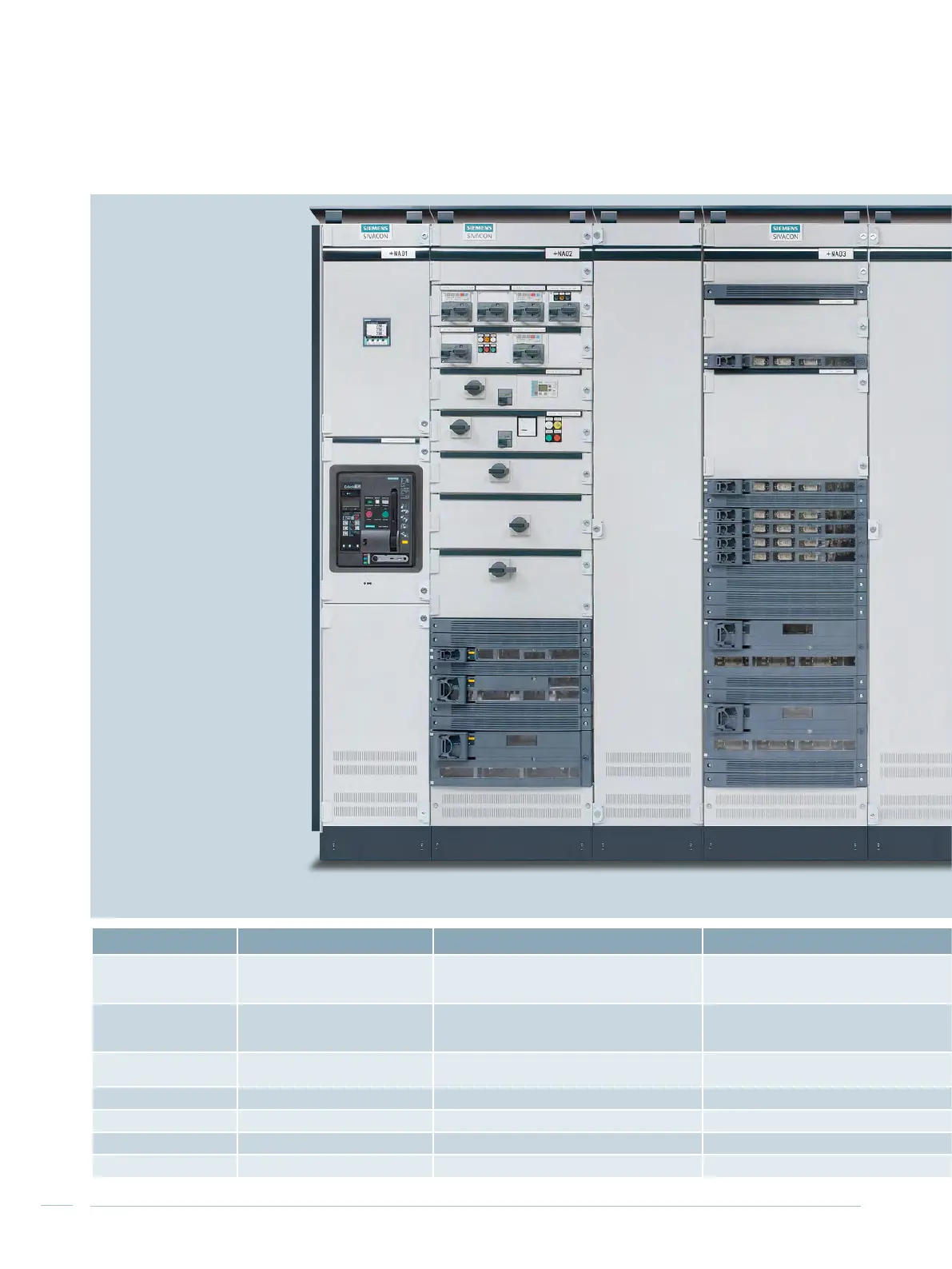
2.5 Overview of mounting designs
Circuit-breaker design Universal mounting design In-line design, plug-in Fixed-mounted design
In-line design,
fixed-mounted
Reactive power compensation
Mounting design
Withdrawable design
Fixed mounted design
Withdrawable design
Fixed-mounted design with compartment doors
Plug-in design
Plug-in design Fixed-mounted design with front covers Fixed mounted design Fixed mounted design
Functions
Incoming unit
Outgoing unit
Coupler
Cable feeders
Motor feeders (MCC)
Cable feeders Cable feeders Cable feeders Central compensation of reactive power
Rated current I
n
Up to 6,300 A Up to 630 A Up to 630 A Up to 630 A Up to 630 A
Non-choked up to 600 kvar
Choked up to 500 kvar
Connection type Front and rear side Front and rear side Front side Front side Front side Front side
Cubicle width 400, 600, 800, 1,000, 1,400 mm 600, 1,000, 1,200 mm 1,000, 1,200 mm 1,000, 1,200 mm 600, 800, 1,000 mm 800 mm
Internal separation Form 1, 2b, 3a, 4b, 4 type 7 (BS) Form 3b, 4a, 4b, 4 type 7 (BS) Form 3b, 4b Form 1, 2b, 3b, 4a, 4b Form 1, 2b Form 1, 2b
Busbar position Rear, top Rear, top Rear, top Rear, top Rear Rear, top, without
Tab. 2/10: Basic data of the different mounting designs

 Loading...


