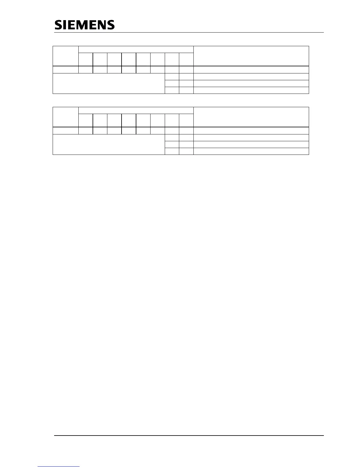
7 6 5 4 3 2 1 0
0FH 0 0 0 0 0 0
User_Prm_Data_Not_Okay
0 0 User_Prm_Finished
0 1 PRM_Conflict
1 1 Not_Allowed
Figure 6.6: Coding User_Prm_Data_Not/_Okay_Cmd
If an additional Set-Param telegram is supposed to be received in the meantime, the signal ‘Prm_Conflict’ is
is returned for the acknowledgement of the first Set_Param telegram, whether positive or negative. Then
the user must repeat the validation because the SPC3 has made a new Prm buffer available.
6.2.3 Check_Config (SAP62)
The user takes on the evaluation of the configuration data. After SPC3 has received a validated
Check_Config-Telegram, SPC3 exchanges the Aux-Puffer1/2 (all data bytes are entered here) for the Cfg
buffer, stores the input data length in ‘R_Len_Cfg-Data,’ and generates ‘New_Cfg_Data-Interrupt’.
The user must then check the ‘User_Config_Data’ and either respond with ‘User_Cfg_Data_Okay_Cmd’ or
with ‘User_Cfg_Data_Not_Okay_Cmd’ (acknowledgement to the Cfg_SM). The net data is input in the
buffer in the format regulation of the standard.
The user response (User_Cfg_Data_Okay_Cmd or the User_Cfg_Data_Not_Okay_Cmd response)
again takes back the ‘New_Cfg_Data’ interrupt and may not be acknowledged in the IAR.
If an incorrect configuration is signalled back, various diagnostics bits are changed, and there is branching
to ‘Wait_Prm.“
For a correct configuration, the transition to ‘DATA_EX’ takes place immediately, if no Din_buffer is present
(R_Len_Din_Puf = 00H) and trigger counters for the parameter setting telegrams and configuration
telegrams are at 0. Otherwise, the transition does not take place until the first ‘New_DIN_Puffer_Cmd’ with
which the user makes the first valid ‘N buffer” available. When entering into ‘DATA_EX,’ SPC3 also
generates the ‘Go/Leave_Data_Exchange-Interrupt.
If the received configuration data from the Cfg buffer are supposed to result in a change of the Read-Cfg-
buffer ( the change contains the data for the Get_Config telegram), the user must make the new Read_Cfg
data available in the Read-Cfg buffer before the ‘User_Cfg_Data_Okay_Cmd” acknowledgement. After
receiving the acknowledgement, SPC3 exchanges the Cfg buffer with the Read-Cfg buffer, if
‘EN_Change_Cfg_buffer = 1’ is set in mode register1.
During the acknowledgement, the user receives information about whether there is a conflict or not. If an
additional Check_Config telegram was supposed to be received in the meantime, the user receives the
‘Cfg_Conflict” signal during the acknowledgement of the first Check_Config telegram, whether positive or
negative. Then the user must repeat the validation, because SPC3 has made a new Cfg buffer available.
The ‘User_Cfg_Data_Okay_Cmd’ and ‘User_Cfg_Data_Not_Okay_Cmd’ acknowledgements are read
accesses to defined memory cells (see Section 2.2.1) with the relevant ‘Not_Allowed’, ‘User_Cfg_Finished,’
or ‘Cfg_Conflict’ signals (see Figure 3.7). If the ‘New_Prm_Data’and ‘New_Cfg_Data’ are supposed to
be present simultaneously during power up, the user must maintain the Set_Param and then the
Check_Config. acknowledgement sequence.