PROFIBUS Interface Center
SPC3
Page 46 V1.3 SPC3 Hardware Description
2003/04 Copyright (C) Siemens AG 2003. All rights reserved.
8.5 Timing Characteristics
The following is generally applicable: All signals beginning with ‘X’ are ‘low active’.
All signal runtimes are based on the capacitive loads specified in the table above.
8.5.1 SYS Bus Interface
Clock Pulse:
No. Parameter MIN MAX Unit
Clock pulse 48 Mhz :
1 Clock High Time 6.25 14.6 ns
2 Clock Low Time 6.25 14.6 ns
3 Rise Time 4 ns
4 Fall Time 4 ns
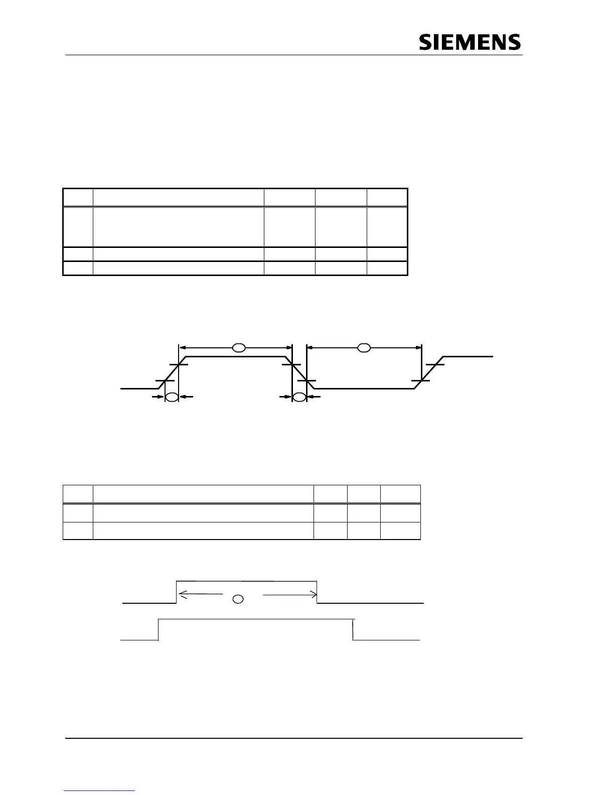
Clock Pulse Timing:
1
CLK
2
TCLH TCLL
2,4V
0,6V
3 4
Distortions in the clock pulse signal are permitted up to a ratio of 40:60. At a threshold of 1.5 or 3.5 V:
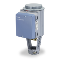
Interrupts:
No. Parameter MIN MAX Unit
1 Interrupt Inactive Time (for EOI_Timebase = 0) 1 1
µs
Interrupt Inactive Time 1 1 ms
X/INT 1
EOI
After acknowledging an interrupt with EO1, a min. of 1 us or 1 ms is expected in SPC3 before a new
interrupt is output.