PROFIBUS Interface Center
SPC3
Page 58 V1.3 SPC3 Hardware Description
2003/04 Copyright (C) Siemens AG 2003. All rights reserved.
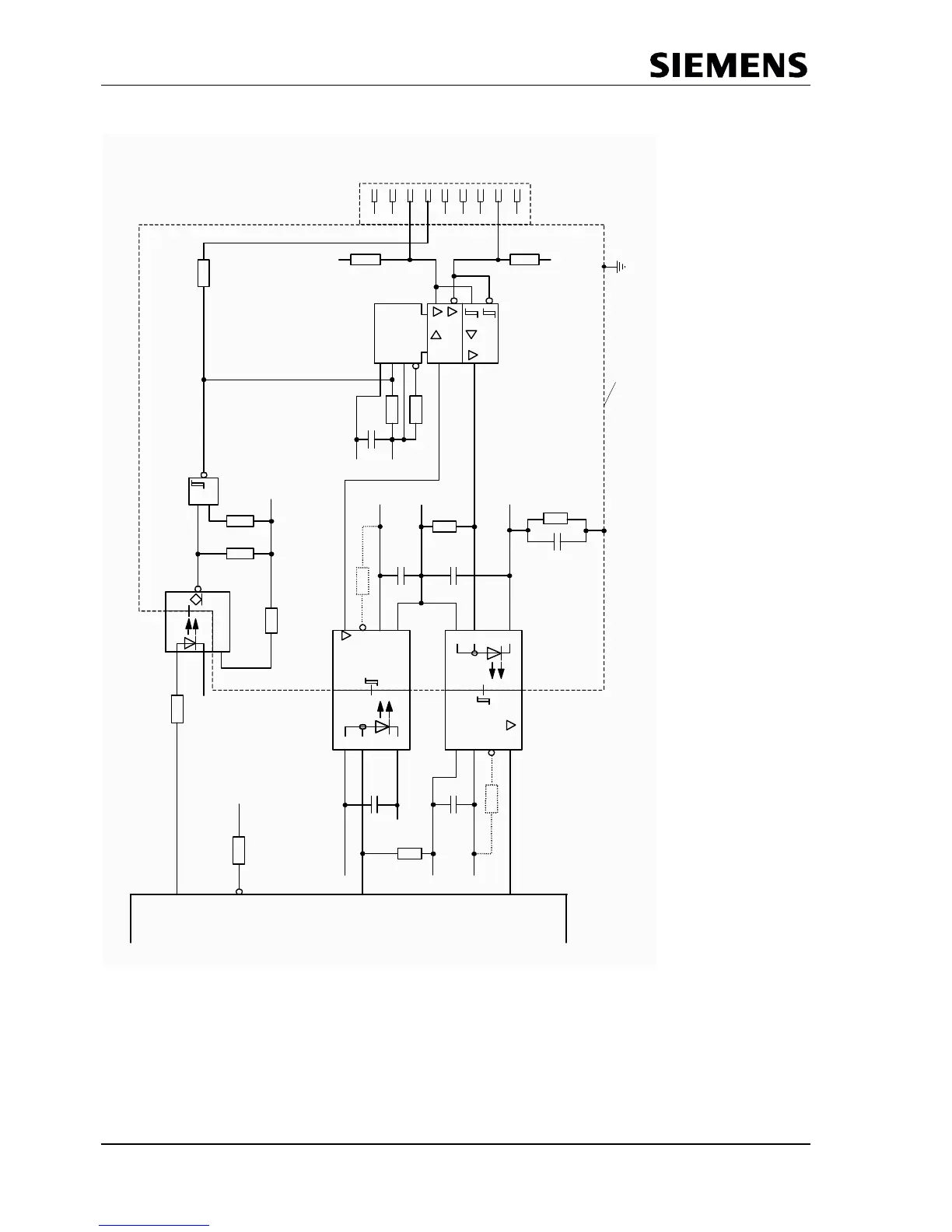
9.2 Example for the RS 485 Interface
SN65ALS1176
1
1
2
U+
EN1
GND
EN2
1
0
0
K
1
0
0
K
2P5
2M
6
8
n
2P5
2M
6
8
0
R
1
K
2
IN
U-
U+
U-
U+
68n
68n
EN
2M
P5
P5
680R
1
K
2
O
U
T
EN
680R
300R
680R
HCPL0601
2P5
&
2
7
4
H
C
1
3
2
3
0
0
R
U+
IN
U-
3
0
0
R
6
8
n
6
8
n
6
8
0
R
O
U
T
EN
U-
U+
20K
M
M
2P5
2M
3
0
0
R
M
C
T
S
R
T
S
T
X
D
R
X
D
B
-
l
i
n
e
R
T
S
2
M
2
P
5
A
-
l
i
n
e
I
m
p
o
r
t
a
n
t
:
e
l
e
c
t
r
i
c
a
l
i
s
o
l
a
t
i
o
n
t
o
b
u
s
P
5
a
n
d
2
P
5
S
h
i
e
l
d
D
r
i
v
e
r
s
e
l
e
c
t
:
D
i
f
f
e
r
e
n
t
i
a
l
v
o
l
t
a
g
e
>
2
V
1
2
3
4
6
7
8
9
L
a
y
o
u
t
:
l
i
n
e
s
m
u
s
t
b
e
k
e
p
t
a
s
s
h
o
r
t
a
s
p
o
s
s
i
b
l
e
.
M
1
M
HCPL7101 / 7721 / 0721
2
.
2
.
.
2
2
n
F
5
0
0
V
HCPL7101 / 7721 / 0721
5
Explanations of the circuitry:
The bus driver input EN2 has to be connected to low potential to ensure that after transmission of a
telegram the ASIC is able to listen to the transmitted data.
To minimize the capacity of the bus lines the user should avoid additional capacities. The typical capacity of
a bus station should be 15 ... 25 pF.