SPC3 PROFIBUS Interface Center
SPC3 Hardware Description V1.3 Page 41
Copyright (C) Siemens AG 2003 All rights reserved. 2003/04
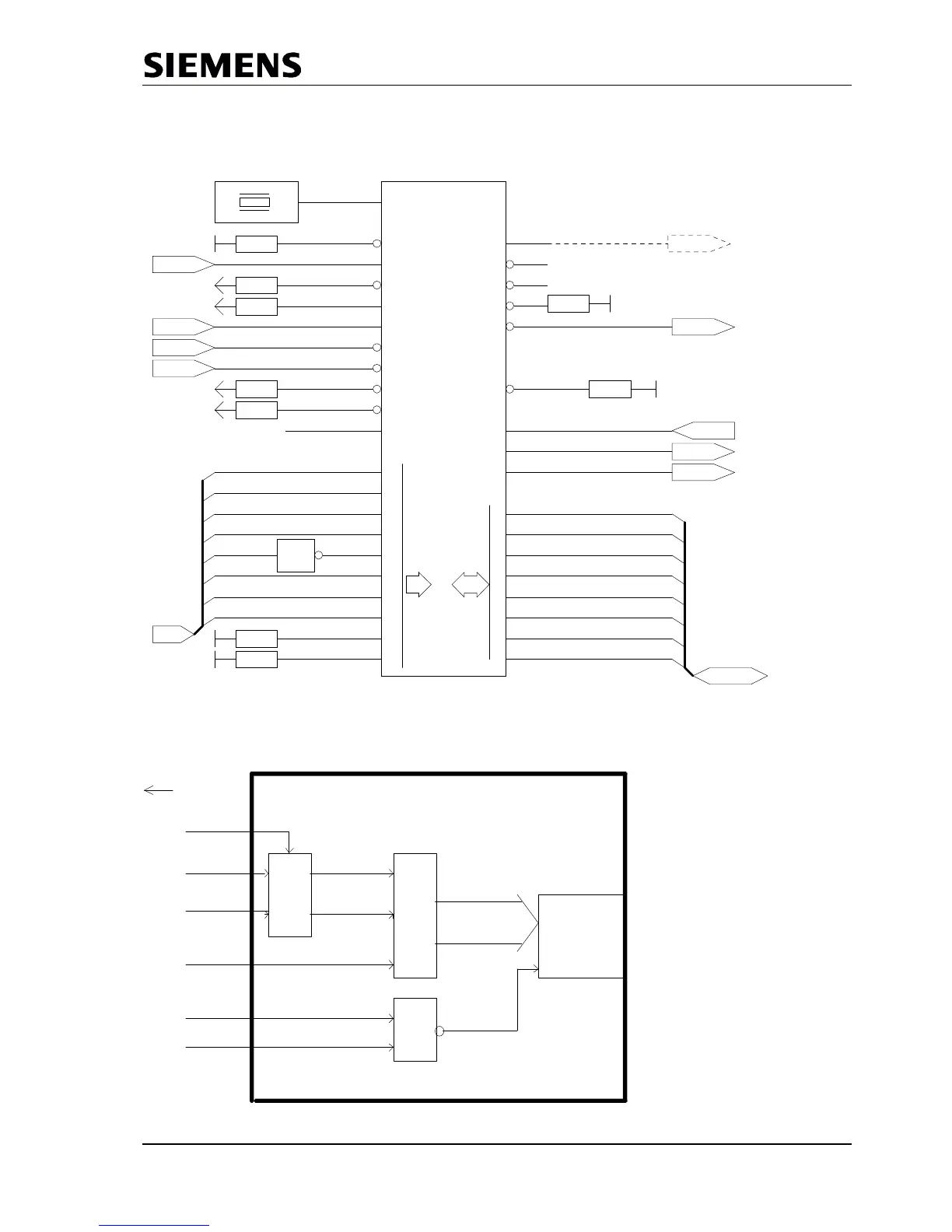
7.1.4 Application with the 80 C 32
CLK
5
48 MHz
3k3
1
P5 XCS
3k3
23
P5 MODE
3k3
34
P5
3k3
35
P5
3
XTEST0
XTEST1
DIVIDER
4
XRD
2
XWR
24
ALE
uC
36
RESET
uC
1
0
1
2
3
4
5
6
7
8
9
1K
M
1K
M
AB
44
43
41
40
37
42
32
31
29
25
0
1
2
3
4
5
6
7
DB
11
12
15
16
19
20
21
22
RXD 30
27
RTS
TXD
26
1K
8
XINT/MOT
M
1K
33
XCTS
9
X/INT
10
AB 10
14
13
7
XREADY
XHOLDT.
CLK2
ADB(8:15)
AB8
AB9
AB10
AB11
AB12
AB13
AB14
AB15
DB(0:7)
ADB0
ADB1
ADB2
ADB3
ADB4
ADB5
ADB6
ADB7
TXD
RTS
RXD
RS485
RS485
RS485
Px.x
uC
uC
uC
uC
uC
SPC3
ALE
XWR
XRD
INT0/1
1K
M
5V or
GND
The pull up / pull down resistances in the drawing above are only relevant for a in circuit tester.The internal
chip select logic is activated when the address pins A 11 .. A 15 are set to „0“ . In the example above the
starting address of the SPC3 is set to 0x1000 .
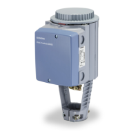
ALE
AD 0 ..7
Processor
SPC 3
A8 .. 10
A 0..10
CS
1,5 kByte RAM
in the SPC 3
A 11..15 alle 0
Addreß-
latch
AD 0 ..7