SPC3 PROFIBUS Interface Center
SPC3 Hardware Description V1.3 Page 19
Copyright (C) Siemens AG 2003 All rights reserved. 2003/04
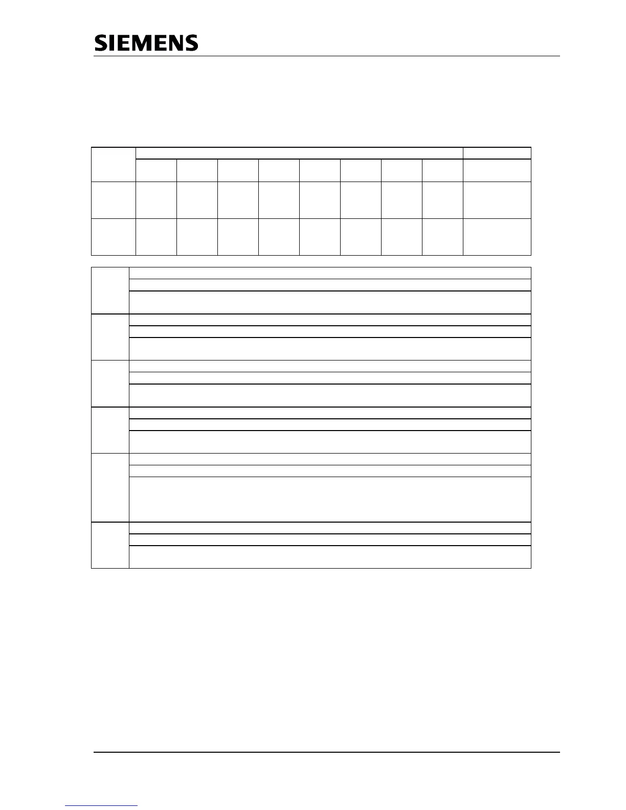
5.1.2 Mode Register 1 (Mode-REG1, writable):
Some control bits must be changed during operation. These control bits are combined in Mode-Register 1
and can be set independently of each other (Mode_Reg_S) or can be deleted independently of each other
(Mode_Reg_R). Various addresses are used for setting and deleting. Log ‘1’ must be written to the bit
position to be set or deleted.
Address Bit Position Designation
Control
Register
EN_
Change_
Cfg_
Puffer
User_
Leave_
Master
Go_
Offline
EOI START_
SPC3
Mode-Reg_R
7..0
Bit 0 START_SPC3
Exiting the Offline state
1 = SPC3 exits offline and goes to passive-idle. In addition, the idle timer and
Wd timer are started and ‘Go_Offline = 0’ is set.
Bit 1 EOI
End of Interrupt
1 = End of Interrupt: SPC3 switches the interrupt outputs to inactive and again
sets EOI to log.’0.’
Bit 2 Go_Offline
Going into the offline state
1 = After the current requests ends, SPC3 goes to the offline state and again
sets Go_Offline to log.’0.’
Bit 3 User_Leave_Master
Request to the DP_SM to go to ‘Wait_Prm.’
1 = The user causes the DP_SM to go to ‘Wait_Prm.’ After this action, SPC3
sets User_Leave_Master to log.’0.’
Bit 4 En_Change_Cfg_Puffer
Enabling buffer exchange (Cfg buffer for Read_Cfg buffer)
0 = With ‘User_Cfg_Data_Okay_Cmd,’ the Cfg buffer may not be exchanged for
the Read_Cfg buffer.
1 = With ‘User_Cfg_Data_Okay_Cmd,’ the Cfg buffer must be exchanged for
the Read_Cfg buffer.
Bit 5 Res_User_Wd
Resetting the User_WD_Timers
1 = SPC3 again sets the User_Wd_Timer to the parameterized value
‘User_Wd_Value
15..0.
’ After this action, SPC3 sets Res_User_Wd to log.’0.’
Figure 5..2: Mode Register1 S and Mode Register1 R Bit7..0.(writable)