SPC3 PROFIBUS Interface Center
SPC3 Hardware Description V1.3 Page 35
Copyright (C) Siemens AG 2003 All rights reserved. 2003/04
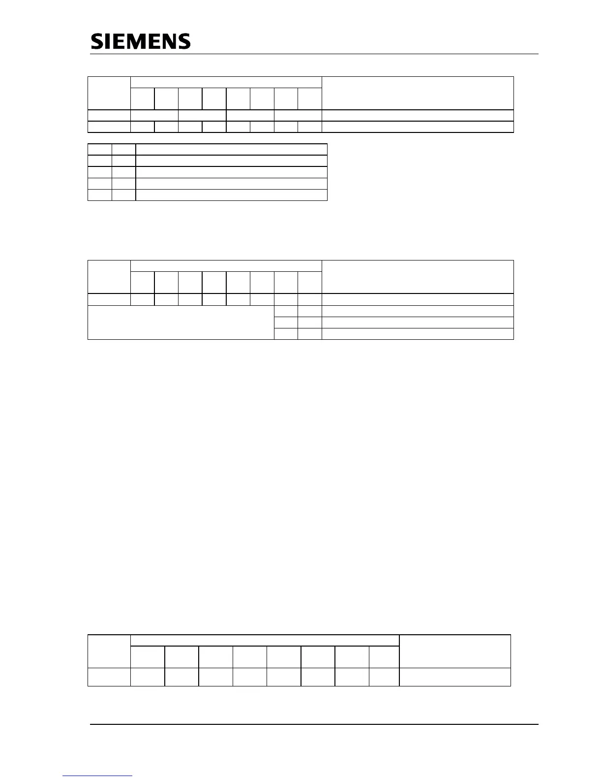
Address Bit Position Designation
Control
Register
7 6 5 4 3 2 0
08H F U N D Din_Buffer_SM
X1 X2 X1 X2 X1 X2 X1 X2 See below for coding.
X1 X2 Coding
0 0 Nil
0 1 Din_Buf_Ptr1
1 0 Din_Buf_Ptr2
1 1 Din_Buf_Ptr3
Figure 6.13: Din_Buffer Management
When reading the ‘New_Din_Buffer_Cmd’ the user gets the information which buffer (U-buffer) belongs to
the user after the change (Din_Buf_Ptr 1-3).
Address Bit Position Designation
Control
Register
7 6 5 4 3 2 1 0
09H 0 0 0 0 0 0
New_Din_Buf_Cmd
0 1 Din_Buf_Ptr1
1 0 Din_Buf_Ptr2
1 1 Din_Buf_Ptr3
Figure 6.14: Next_Din_Buffer_Cmd
6.2.5.3 User_Watchdog_Timer
After power-up (‘DATA_EX’ state), it is possible that SPC3 continually answers Write_Read_Data-telegrams
without the user fetching the received Din buffers or making new Dout buffers available. If the user
processor ‘hangs up,’ the master would not receive this information. Therefore, a ‘User_Watchdog_Timer’
is implemented in SPC3.
This User_Wd_Timer is an internal 16-bit RAM cell that is started from a ‘R_User_Wd_Value
15..0
’ value the
user parameterizes and is decremented with each received Write_Read_Data telegram from SPC3. If the
timer attains the ‘0000hex’ value, SPC3 transitions to the ‘Wait_Prm’ state, and the DP_SM carries out a
‘Leave_Master.’ The user must cyclically set this timer to its start value. Therefore, ‘Res_User_Wd = 1’
must be set in mode register 1. Upon receipt of the next Write_Read_Data telegram, SPC3 again loads the
User_Wd_Timer to the parameterized value ‘R_User_Wd_Value
15..0
’ and sets ‘Res_User_Wd = 0’ (Mode
Register 1). During power-up, the user must also set ‘Res_User_Wd = 1’, so that the User_Wd_Timer is
even set at its parameterized value.
6.2.6 Global_Control (SAP58)
SPC3 itself processes the Global_Control-Telegrams in the manner already described. In addition, this
information is available to the user.
The first byte of a valid Global_Control command is stored in the R_GC_Comand RAM cell. The second
telegram byte (Group_Select) is processed internally.
Address Bit Position Designation
RAM
Cell
7 6 5 4 3 2 1 0
3CH
Res Res Sync Un
sync
Freeze Un
freeze
Clear_
Data
Res
R_GC_Command