SPC3 PROFIBUS Interface Center
SPC3 Hardware Description V1.3 Page 51
Copyright (C) Siemens AG 2003 All rights reserved. 2003/04
The request for a read access to SPC3 is derived from the positive edge of the E clock (in addition: XCS =
0, R W = 1). The request for a write access is derived from the negative edge of the E clock (in addition:
XCS = 0, R W = 0).
AMI-Vers.
ST-Vers.
No. Parameter Min Max Min Max Unit
40 E_Clock-Pulse-Width
74.2
3T + 74.2
ns
41
Address (AB
10..0
) Setuptime to E_Clock ↑
10
10
ns
42
Address (AB
10..0
) Holdtime after E_Clock ↓
5
5
ns
43
E_Clock ↑ to Data Active Delay
5.7 17
5
ns
44
E_Clock ↑ to Data valid (Zugriff auf RAM)
4T + 5
(88,3)
3T + 44.2
(107)
ns
E_Clock ↑ to Data valid (Zugriff auf die Register)
4T + 18
(101,3)
4T + 21.9
(105,2)
ns
45
Data Holdtime after E_Clock ↓
2 6.3
4 12
ns
46
R_W Setuptime to E_Clock ↑
10
10
ns
47
R_W Holdtime after E_Clock ↓
5
5
ns
48
XCS Setuptime to E_Clock ↑
0
0
ns
49
XCS Holdtime after E_Clock ↓
0
0
ns
50
Data Setuptime to E_Clock ↓
10
10
ns
51
Data Holdtime after E_Clock ↓
10
10
ns
Explanations:
T = Clock pulse cycle (48MHz)
TBD = to be defined
(1
= Access to the RAM
(2
= Access to the registers/latches
(3
= For T = 48 MHz
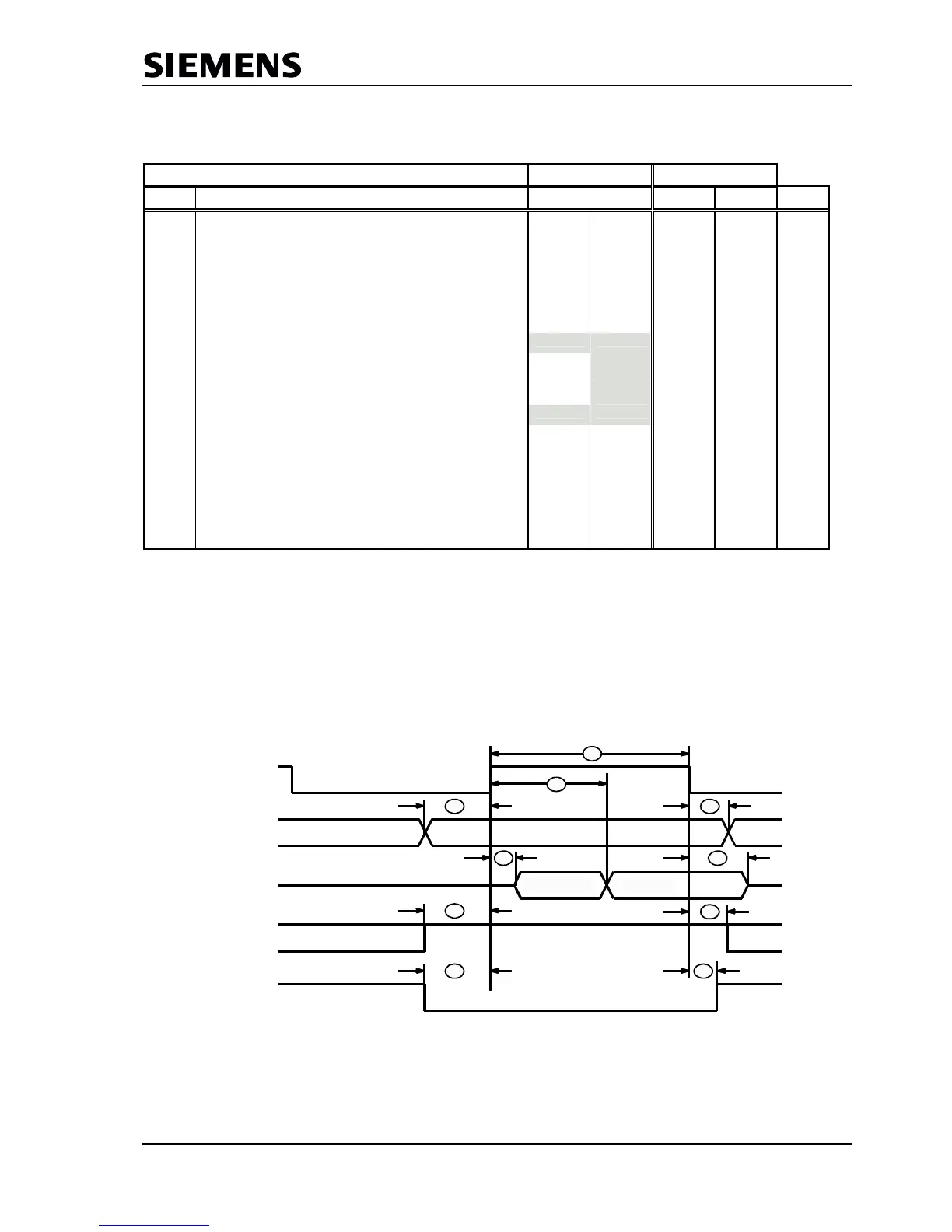
Synchronous Motorola-Mode, Processor-Read-Timing
R_W
VALID
Data Valid
AB(10..0)
DB(7..0)
XCS
AS = log.'1'
E_Clock
41
Data Invalid
40
44
43
46
48 49
47
45
42