PROFIBUS Interface Center
SPC3
Page 62 V1.3 SPC3 Hardware Description
2003/04 Copyright (C) Siemens AG 2003. All rights reserved.
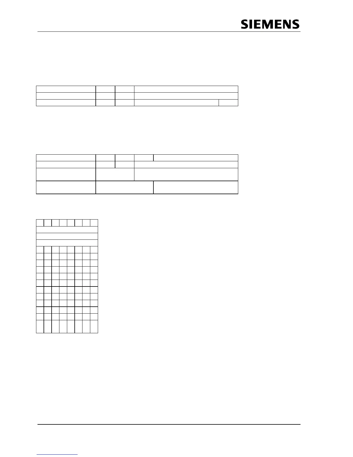
Identifier-Related Diagnostics:
For each identifier byte assigned during configuration (for example, 0 x 10 for 1 byte input), a bit is
reserved.
In the case of a modular system with an identifier byte each per module, module-specific diagnostics can be
indicated. One bit respectively will then indicate diagnostics per module.
Bit 7 Bit 6 Bit 5-0
Header Byte
0 1
Block length in bytes including header
Bit Structure 1 1
Identifier Byte 7 has etc.
Identifier Byte 0 has
diagnostics diagnostics
Channel-Related Diagnostics:
In this block, the diagnosed channels and the diagnostics cause are entered in sequence. Three bits are
required per entry.
Bit 7 Bit 6 Bit 5 Bit 4 - 0
Header Byte
1 0
Identification Number
Channel Number Coding
Input/Output
Channel Number
Type of Diagnostics Coding
Channel Type
Coding
Error Type
Coding of the error type is in part manufacturer-specific; other codings are specified in the Standard.
Example:
Status
If the Bit EXT_DIAG is set to 0 , data is viewed as status info from the system view. f.e. cancellation of the
error triggering the diagnostics.
0
Device-related diagnostics.
Device-specific Meaning of the bits
diagnostics field of is specified
length 3 manufacturer-specific.
0