Mounting
12 / 60
5 Mounting
5.1 General information on mounting
Use detailed dimension drawings for photometer and control device mounting.
l
Distance between photometer and stray light sources > 2 m.
l
Avoid the formation of gas bubbles on the sensor head by using a suitable fitting position.
l
Distance between the photometer and pipe bends and cross-section-changing elements > 1 m.
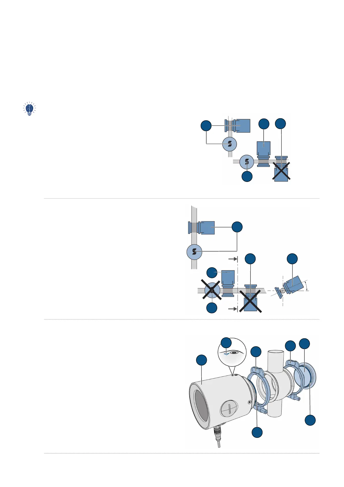
5.2 Mounting position of the photometer
For vertical fitting, the plugs must point downwards. For horizontal fitting, the plugs should be on the left side.
In process line
Fitting position (A) and (B): Permitted
Fitting position (C): Permissible under the following con-
ditions:
l
Medium temperature:
–
-10 ... +80° C
–
120° C max. 2 h
–
150° C max. 1 h
l
Continuous medium flow at > 2 bar pressure
Fitting position (D): Impermissible
EHEDG-compliant
Fitting positions (A), (C) and (E): Permitted
Fitting position (B) and (D): Impermissible
5.3 Fitting in VARINLINE
®
connector
u
Mount photometer (1) including seal (7) with clamp
ring (3) on VARINLINE
®
connector.
u
Make sure that the marking (2) points in the flow di-
rection.
u
Mount blanking plate (5), including seal (6) with
clamp ring (4) on VARINLINE
®
connector.
 Loading...