Electrical installation
14 / 60
6 Electrical installation
DANGER
Danger due to improper connection of the operating voltage.
Improper connection of the electrical service voltage can be life-threatening. The system can also be damaged in
the process.
u
Connection must be carried out by a specialist in accordance with local regulations.
u
Install a disconnecting device near the power supply to disconnect the device from the mains. The discon-
necting device should be easily accessible and labelled.
u
Use shielded cables and connect the cable shield to earth.
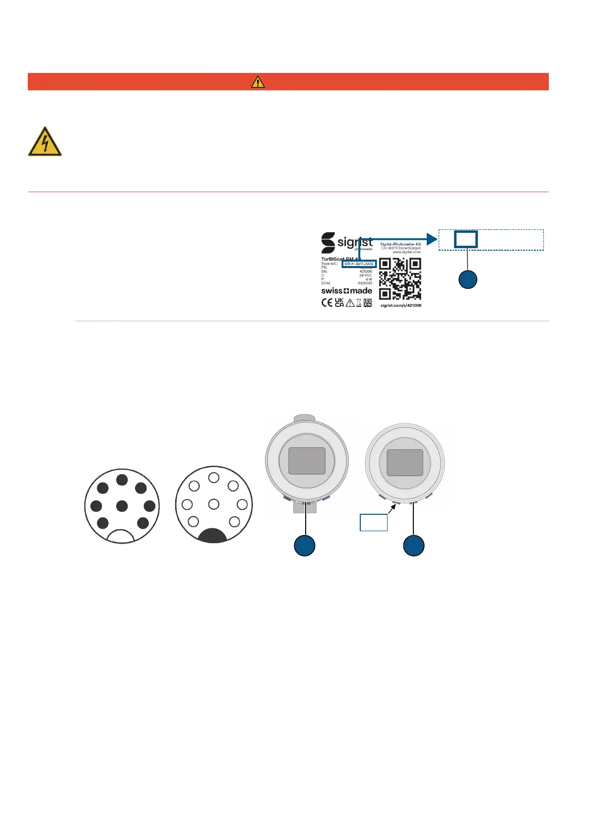
6.1 Determine communication module
The integrated communication module can be seen on
the nameplate [}11]. The following codes (1) are possi-
ble: IO = EG_IO | PE = EG_PoE | PB = EG_Profibus |
PN = EG_Profinet
6.2 Photometer connection
A distinction is made between two variants:
l
Photometer (PM) with integrated display and connections
1)
l
Photometer (PM) without display connected with SiDis AD 40
2)
6.2.1 EG_IO
1
2
8
3
4
5
6
7
Male (A)
A A
PM SiDis
PM
Female PM
3
7
2
1
8
4
6
5
1) 2)
(A) M12 8-pin connector A Coded
Function Designation Plug pin no. Colour
GND GND 1 white
24V 24V 2 brown
RS485 Modbus RTU
Configurable with or without 120 Ω termination.
Function Designation Plug pin no. Colour
A IO1 7 blue
B IO2 5 grey
 Loading...