Notes and requirements for installation and operation VE
- 26 - © SIKA • Ea4500_VE • 02/2019
3 Notes and requirements for installation and operation
Observe the following instructions to achieve the highest possible measurement accuracy
and the specified output signal:
• A screw-in sleeve with female thread G½ is required for installation in the pipeline.
• If the flow monitor cannot be easily screwed in, do not rework or re-cut its thread under
any circumstances. This will destroy the flow sensor. If necessary, you can rework the in-
ternal thread of the screw-in sleeve.
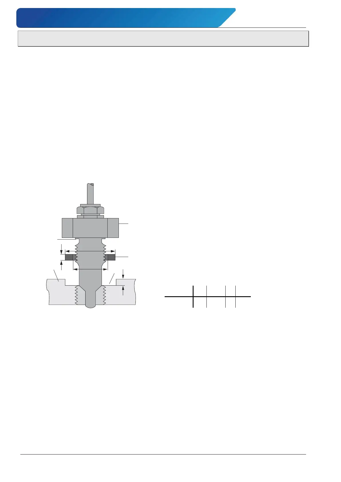
• The sealing is done with a flat gasket which is centred on the sensor by the guide shoul-
der. Make sure that the sleeve has a flat sealing surface.
• You can also seal the thread using PTFE sealing tape or liquid sealant.
• For pressures above 30 bar, you must provide a chamber to prevent the gasket from de-
flecting under high loads. PTFE gaskets must generally be chambered. For high pressure
applications you must use metal gaskets.
• The standard material for gaskets is AFM 34.
1: Sensor
2: Flat gasket
3: Chamber
4: Shoulder
5: Counterpart
Dimensions of gasket
21 27,5 2 1,5
Fig. 1.: Installation of flow monitor
(applies to VES and VEG)
 Loading...