VE Commissioning
Technical changes reserved - 31 -
6 Commissioning
Connect the installed flow monitor to the operating voltage.
After applying the supply voltage, the LED strip indicates full deflection for approx.
10-15 s (LED test).
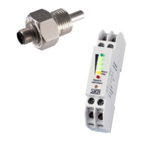
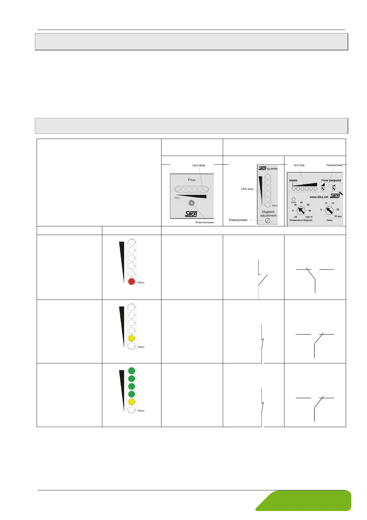
On the front side of the flow monitor, there are LED strips and potentiometers for setting the
setpoints.
6.1 LED and switching contact functions
Compact version
VES08 and VES09
Separate version
VEG08 und VEG09
Switching contact functions
stopped or the flow
has fallen below the
specified value.
Transistor
switching output:
~ 0 V
Relay contact:
Relay changeover
contact:
has been reached.
Transistor
switching output:
~ 24 V
Relay contact:
Relay changeover
contact:
has been exceeded.
The “flow reserve”
is sufficient.
Transistor
switching output:
~ 24 V
Relay contact:
Relay changeover
contact:
 Loading...