Electrical connection VE
- 28 - © SIKA • Ea4500_VE • 02/2019
5 Electrical connection
We recommend using only shielded connection cables, whereby the shield must be grounded
at one end (on the side of the wire ends).
5.1 VES08 and VES09 with integrated evaluation electronics
The VES is designed exclusively for a supply voltage of 24 VDC ±20 %.
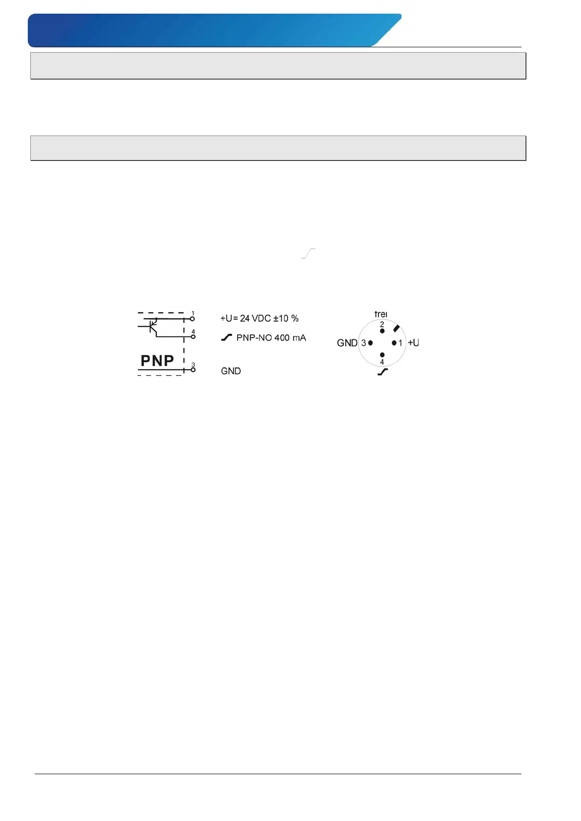
The output is a PNP switching open collector signal.
The output current must not exceed 400 mA DC.
Schematic representation
The connection is made via 3 wires; the supply voltage must be applied between +U and GND
(ground), the output signal can be tapped between and GND. The electrical connection
and the pin assignment of the plug are shown in the wiring diagram (Fig. 3). The connection
diagram can also be found on the type plate of the flow monitor.
Fig. 3: Wiring diagram VES
 Loading...