VE Electrical connection
Technical changes reserved - 29 -
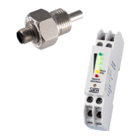
5.2 VEG08 and VEG09 with switching transducer EU 3011V0000126 (24 VDC)
The switching transducer is operated with 24 VDC ±20 %.
The output signal is a relay contact.
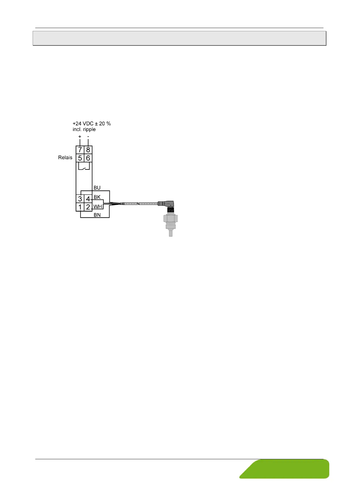
Schematic representation
The flow monitor is connected to the switching transducer with a 4-wire connecting cable
(not included in delivery). The colour assignment of the connection cable is shown in the con-
nection diagram (Fig. 4). The connection diagram can also be found on the type plate of the
switching transducer.
BU: blue
BK: black
WH: white
BN: brown
Fig. 4: Connection diagram switching transducer
EU 3011V0000126 (24 VDC)
 Loading...