Operating manual - English DUO
Copyright Silca 2 010 13
6.4
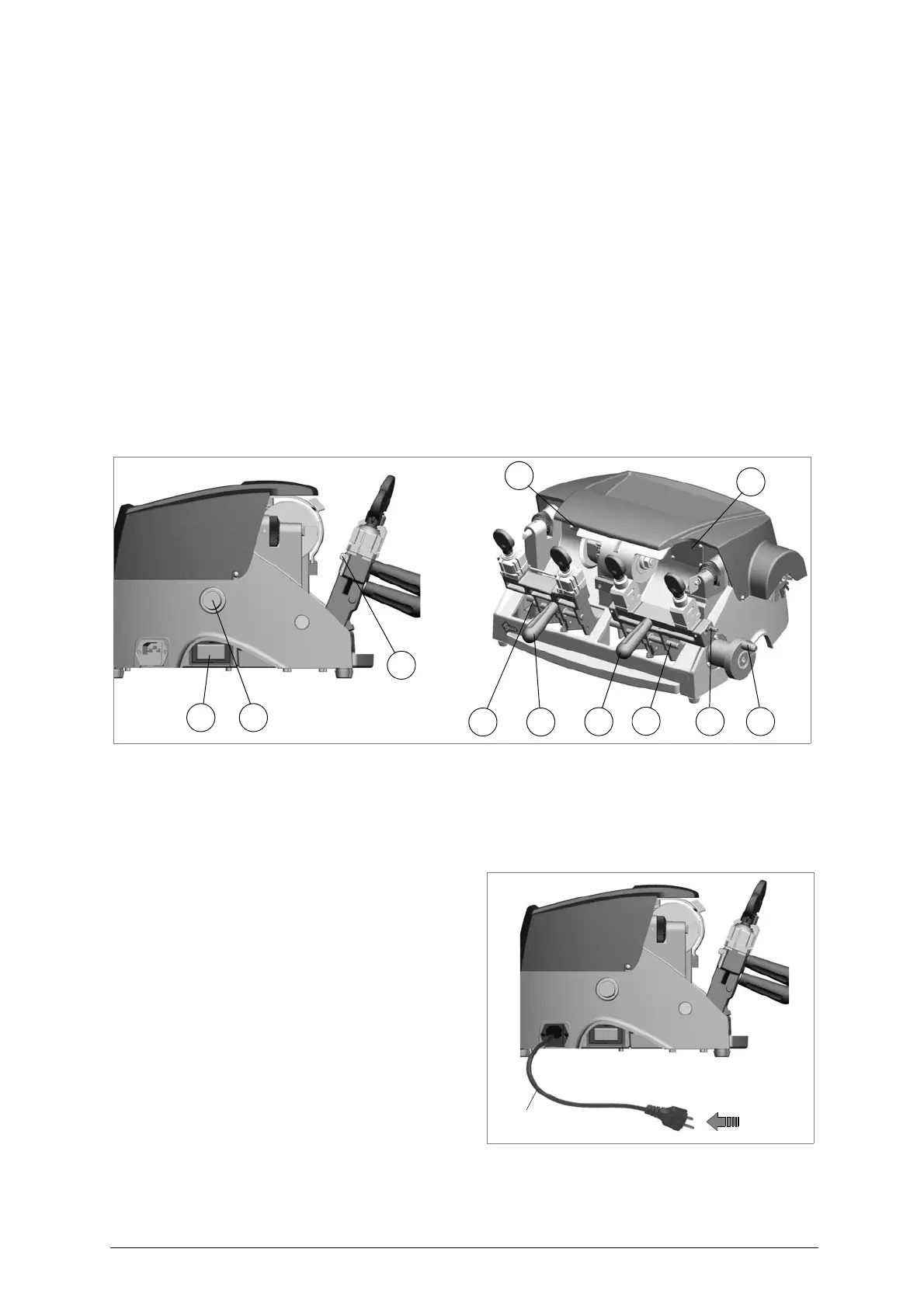
Description of work station
The key-cutting machine needs only one operator, who has the following controls at his/her disposal
:
- Main switch (T), located on the left-hand side of the machine, it activates the machine and turn on
the lamps (R).
- Motor on switch (U), located on the left-hand side of the machine has a warning light to show that
the key-cutting machine is live.
Left-hand carriage:
- Carriage lever (C)
- Carriage release pin (A1) (not available on Duo Brazil version)
- Gauges knob (D1)
- Carriage advancement flywheel (O) (with carriage locked - chap. 8.1.3, page 21) (not available on
Duo Brazil version).
Right-hand carriage:
- Carriage lever (H)
- Carriage release pin (B1) (not available on Duo Brazil version)
- Carriage advancement flywheel (O) (with carriage locked - chap. 8.1.3, page 21) (not available on
Duo Brazil version).
- Tilting movement activating pin (L)
Fig. 9
(*) not available on Duo Brazil version
6.5
Separate parts
The separately packed parts must be installed on the DUO key-cutting machine by the p urchaser, as
follows:
Connection wire
Connect the key-cutting machine power cable
to the electricity mains (fig. 10).
Fig. 10
6.6
Connection to the mains
For the safety of the operator and the machine it is important to ensure that the machine is connected
to the proper mains voltage by means of an earthed differential switch.
power
cable
electricity
supply