Operating manual - English DUO
Copyright Silca 2 010 37
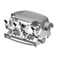
Right-hand tracer point:
ATTENZIONE:
remove the mains plug
.
1) Loosen the screw (N4).
2) Remove the worn tracer point (N).
3) Fit the new tracer point, pushing all the way in. En sure
that the seat is clean.
4) Tighten the screw (N4).
5) Re-calibrate the m achine, foll owing the proce dure de -
scribed in chap. 7.3, page 17.
Fig. 53
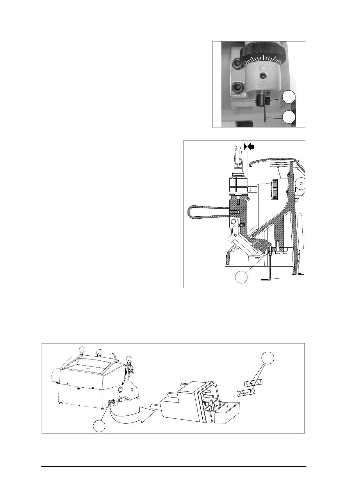
9.6 Regulating left carriage depth
The carriage o n the DU O can be regula ted to
protect the clamps from co ming into contact
with the tracer point or cutting tool.
ATTENTION: the play between cutting too or tracer point
and clamps must be at least 0.1 mm.
Should it be different from this, pro ceed as fol-
lows:
ATTENTION: remove the mains plug.
1) Release the carriage, raise against the cut-
ting tool and take to the end of its run (fig. )
2) Remove the chippings tray (S).
3) Release the nut (S3) (fig. ) with the spanner.
4) Use the Al len wr ench to screw or unscrew
the grub screw in order to move the carriage
away from o r towards the tracer point an d
cutting tool.
5) Tighten the nut.
Fig. 54
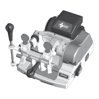
9.7 Replacing the fuses
ATTENTION: remove the mains plug.
1) Unplug the power cable from the key-cutting machine socket.
2) Remove the fuses box placed below the key-cutting machine socket (V) (fig. 55).
3) Replace the fuses (V1) (fig. 55).
4) Close the fuses box and connect the power cable
ATTENTION: fuses must always be replaced with others of the same type (rapid) and with the same Amps (4
Amp for 230V - 8 Amp for 120V).
Fig. 55