22
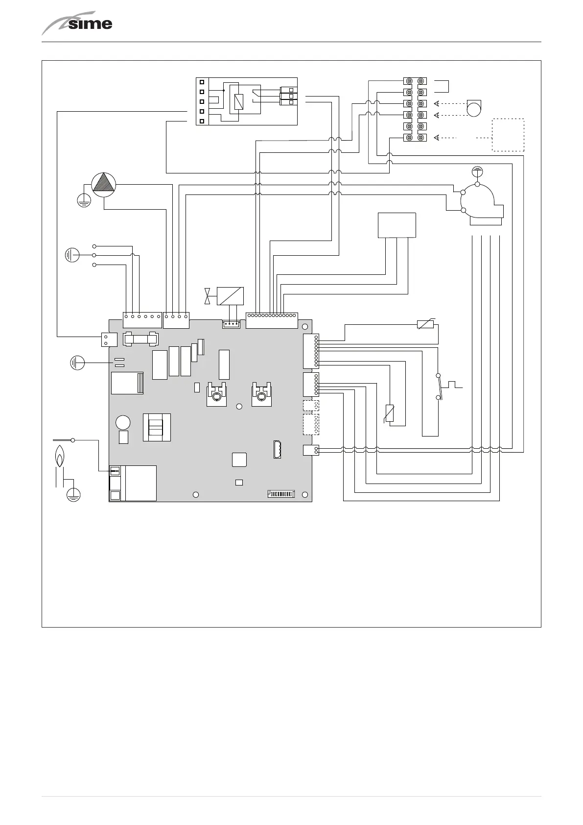
5.11 Wiring diagram
TRA
EVG1-2
F
CN11
BR
BL
BL
PI
BL
BR
230 V - 50 Hz
L
N
CN6
CN5
CN3
CN17
CN4 CN1
CN15
CN14
CN13CN12
CN2
R
R
TPA
V
SF
TS
SMC
GND
OUT
+5V
BK
BK
BL
BL
BK
G
R
BL
4 3 2 1
BL
BK
G
R
BL
BR
EAR
R
OR
G
BK
BK
6
7
8
3
4
5
2
1
N
TA
230V
6
5
4
3
2
1
TA1
SE
BK
BK
BL
BK
BL
BL
BR
BL
BR
Y/S
PLAN
L
Live
N
Neutral
FU
Fuse (3.15AT)
TRA
Ignition transformer
PI
Pump
V
Fan
EAR
Ignition / Detection elec-
trode
EVG1-2
Gas solenoid valve
SMC
Boiler delivery sensor
TS
Safety thermostat
SF
Exhaust sensor
TPA
Water pressure trans-
ducer
TA1
Room Thermostat 1
TA 230V
Room Thermostat 230V
SE
External sensor
BL
Blue
BR
Brown
BK
Black
G
Green
OR
Orange
R
Red
WH
White
To connect the "TA1" remove the jumper between terminals 5-6.
Fig. 14
m
CAUTION
Installer must:
– To mount an omnipolar residual-current circuit
breaker conforming to EN standards
that allows for
completely disconnecting the system in overvoltage
category III conditions (that is, with a gap of at least 3
mm between the open contacts)
.
– Respect the connections L (Live) - N (Neutral).
– Ensure that the special power cable is only re-
placed with a cable ordered as a spare part and
connected by professionally qualified personnel.
m
CAUTION
Installer must:
– Connect the earth wire to an effective earthing
system.
Sime declines all responsible for any injury
or damage to persons, animals,or property as a result
of failure to provide adequate earthing of the appli-
ance
.
d
DO NOT
Do not use water pipes for earthing the appliance.