31
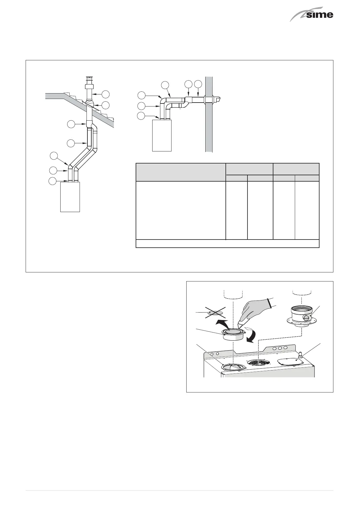
6.12.3 Installation of separate ducts 80mm
The boiler can be installed with separate air inlet and exhaust ducts. The figure below illustrate some examples of the fluing
options allowed and the associated losses of the accessories. The total load loss is the sum of the load losses of the accessories
used. The maximum load loss
must not exceed 15 mm H2O
, and the maximum flue length
must not exceed 25 m
inelt and exhaust.
9
C33
11
10
3
1
1
3
3
7
3
12
12
12
C13
3
2
3
1
14
12
13
12
NOTE
Before connecting accessories, it is
always advisable to lubricate the
internal part of the gaskets with
silicon products. Avoid using oils
and greases.
Load loss - mm H2O Load loss - mm H2O
Inlet Exhaust Inlet Exhaust
1 Air/smoke divider, code 8093050 0 0 0 0
2 90° bend, code 8077450 0.20 0.25 0.25 0.30
3 a Extension 80mm L. 1000, code 8077351 0.15 0.15 0.20 0.20
3 b Extension 80mm L. 500, code 8077350 0.075 0.075 0.10 0.10
7 45° bend, code 8077451 0.15 0.15 0.20 0.20
9 Inlet/ exhaust fitting, code 8091401 -- -- -- --
10 Articulated tile, code 8091300 -- -- -- --
11 Vertical roof terminal, code 8091204 * 0.80 0.10 1.10 0.15
13 Inlet/ exhaust fitting, code 8091401 -- -- -- --
14 Coaxial Terminal, code 8091204 * 0.80 0.10 1.10 0.15
* This loss includes the losses with use of item 9 or 13
GIULIA SYSTEM 25 GIULIA SYSTEM 25
Fig. 25
Plug/socket for attaching the air inlet pipe (separate ducts)
The plug (1) must be modified as detailed below before it can
be used:
– disassemble the plug (1) from the boiler
– remove the pre-cut bottom (2) from inside the plug
– turn the plug over and refit it on the opening it was removed
from, first slotting in the gasket (3). The cylindrical part
should be facing upwards; the first part of the piping will be
attached here.
NOTE:
If the combustion air inlet duct needs to be connected to
the right attachment, move the air inlet closing plate (4) from
the right to the left and proceed with modifying the plug (1) as
described above.
5
4
1
3
2
Fig. 26
KEY:
1
Plug/socket for attaching the air inlet pipe (separate ducts)
2
Pre-cut bottom
3
Gasket
4
Air inlet closing plate
5
Smoke outlet collar