43
In the event of a fault/malfunction the message
"ALL"
will ap-
pear on the display with the alarm number eg.
"ALL 05"
(Deliv-
ery sensor (SM) fault).
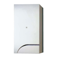
Before repairing the fault:
– disconnect the appliance from the mains power by setting
the main switch to "OFF"
Fig. 49
– as a precautionary measure, close the gas isolation valve.
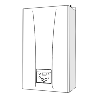
Resolve the problem and start-up the boiler again.
NOTE:
after having repaired the fault, when the alarm number
appears on the display together with the message RESET (see
figure), press the button
o
(
R
) for approximately 3 sec-
onds to start the appliance up again.
7.5 Display of operating data and counters
Access the operating data
"In"
and the counters
"CO"
as fol-
lows:
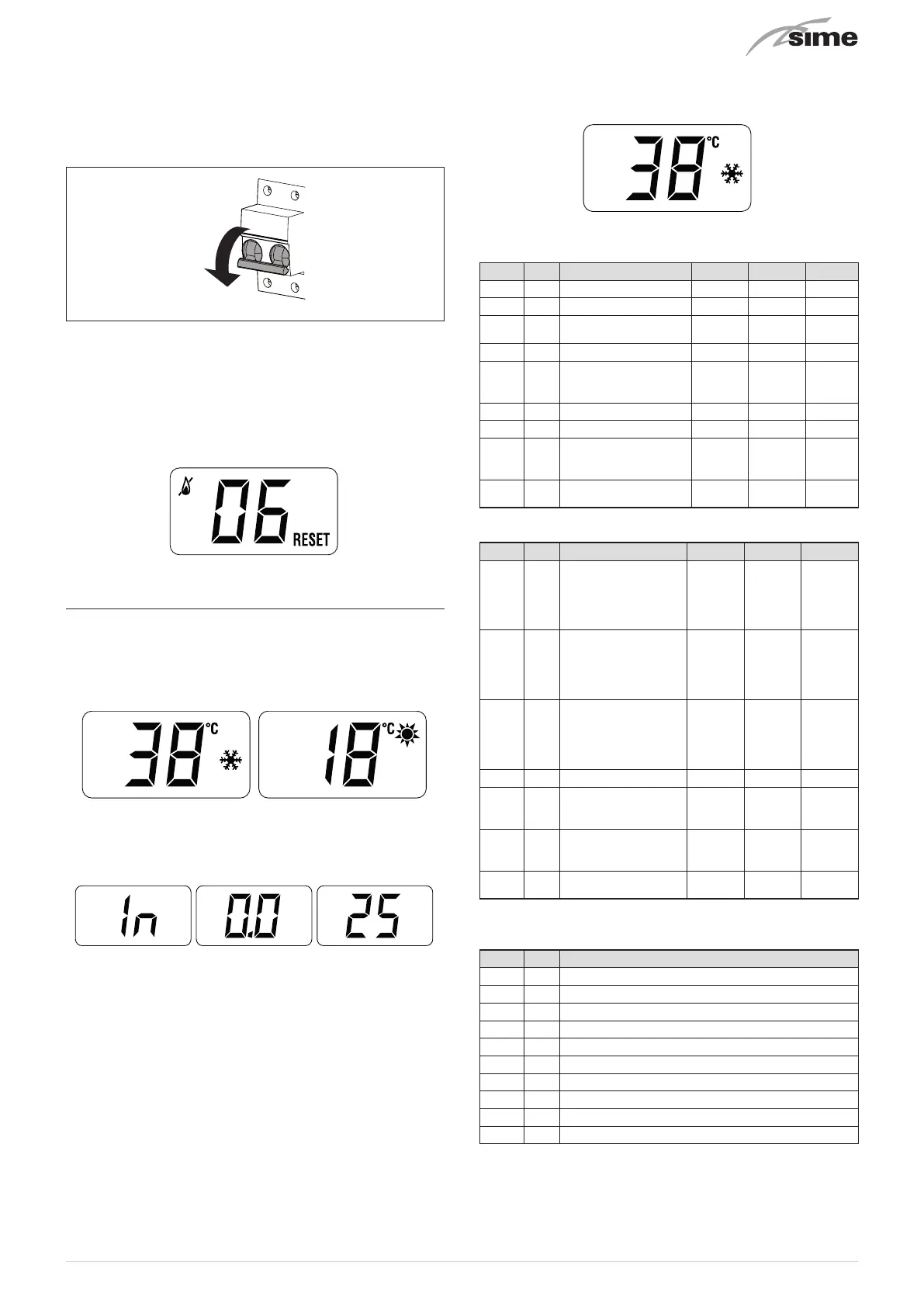
– from the operating screen in the mode enabled at that mo-
ment (WINTER
n
or SUMMER
l
)
– go into
"INFO"
by pressing the buttons
>
and
<
at the same
time
for more than 3 seconds until
"In"
appears alternating
with
"0.0"
(information number) and
"25"
(eg. value)
From this point, the technician has 2 options:
– scroll through the list of
"info"
and
"counters"
by pressing
the button
>
. This way, scrolling will be in sequence
– display the
“activated alarms”
(no more than 10) by pressing
the button
<
. Once in this section, proceed with button
>
or
<
.
When all the values have been displayed, exit the menu by
pressing and holding down the button
o
for approximately 5
seconds until the initial screen is displayed.
TABLE OF INFORMATION DISPLAYED
Type No. Description Range U/M Step
In 0.0 SW version
In 0.1 External sensor - 9 .. 99 °C 1
In 0.2
Delivery sensor
temperature
- 9 .. 99 °C 1
In 0.3 Exhaust temperature - 9 .. 99 °C 1
In 0.6
Actual heating SET
temperature
Par. 13
… Par.
14
°C 1
In 0.7 Power level 0 .. 99 % 1
In 0.8 DHW Flow rate 0 .. 99 l/min 0.1
In 0.9
Water pressure
transducer reading
(when fitted)
0 .. 99 bar 0.1
In 1.0
Actual speed fan
number
0 .. 99
RPM x
100
1
TABLE OF COUNTER DISPLAYED
Type No. Description Range U/M Step
CO 0.0
total no. of boiler
operating hours
0 .. 99 h x 1000
0.1;
from 0.0
to 9.9; 1;
from 10
to 99
CO 0.1
total no. of burner
operating hours
0 .. 99 h x 1000
0.1;
from 0.0
to 9.9; 1;
from 10
to 99
CO 0.2
total no. of burner
ignitions
0 .. 99 h x 1000
0.1;
from 0.0
to 9.9; 1;
from 10
to 99
CO 0.3 total no. faults 0 .. 99 x 1 1
CO 0.4
total no. of times
installer parameters
"tS"accessed
0 .. 99 x 1 1
CO 0.5
total no. of times
OEM parameters
accessed
0 .. 99 x 1 1
CO 0.6
Countdown to the
next service
1 .. 199 months 1
TABLE OF ACTIVATED ALARMS/FAULTS
Type No. Description
AL 0.0 Last activated alarm/fault
AL 0.1 Last but one activated alarm/fault
AL 0.2 Third from last activated alarm/fault
AL 0.3 Previous activated alarm/fault
AL 0.4 Previous activated alarm/fault
AL 0.5 Previous activated alarm/fault
AL 0.6 Previous activated alarm/fault
AL 0.7 Previous activated alarm/fault
AL 0.8 Previous activated alarm/fault
AL 0.9 Previous activated alarm/fault