48
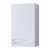
– Unscrew the four nuts (10) securing the combustion cham-
ber door (11)
– pull the fan/sleeve/door unit (12) forwards and remove it
10
10
11
12
Fig. 61
m
CAUTION
Work carefully when removing the assembly (12) to pre-
vent any damage occurring to the internal insulation of
the combus
tion chamber and the door seal.
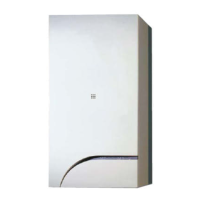
– loosen the four nuts (13) securing the fan (14) and remove it.
14
13
Fig. 62
8.3.2 Cleaning the burner and the combustion
chamber
The combustion chamber and the burner do not require any
particular maintenance. Simply brush them with a soft brush.
8.3.3 Checking the ignition/detection electrode
Check the state of the ignition/detection electrode and replace
if necessary. Check the measurements as per the drawing
whether the ignition/detection electrode is replaced or not.
7,5
±1,0
Fig. 63
8.3.4 Final operations
After having cleaned the combustion chamber and the burner:
– remove any carbon residue
– check that the seal and the insulation of the door (11) to the
combustion chamber are undamaged. Replace if necessary
– refit the assembly by carrying out the same operations for
removal but in the reverse order and tighten the screws (10)
of the door to the combustion chamber
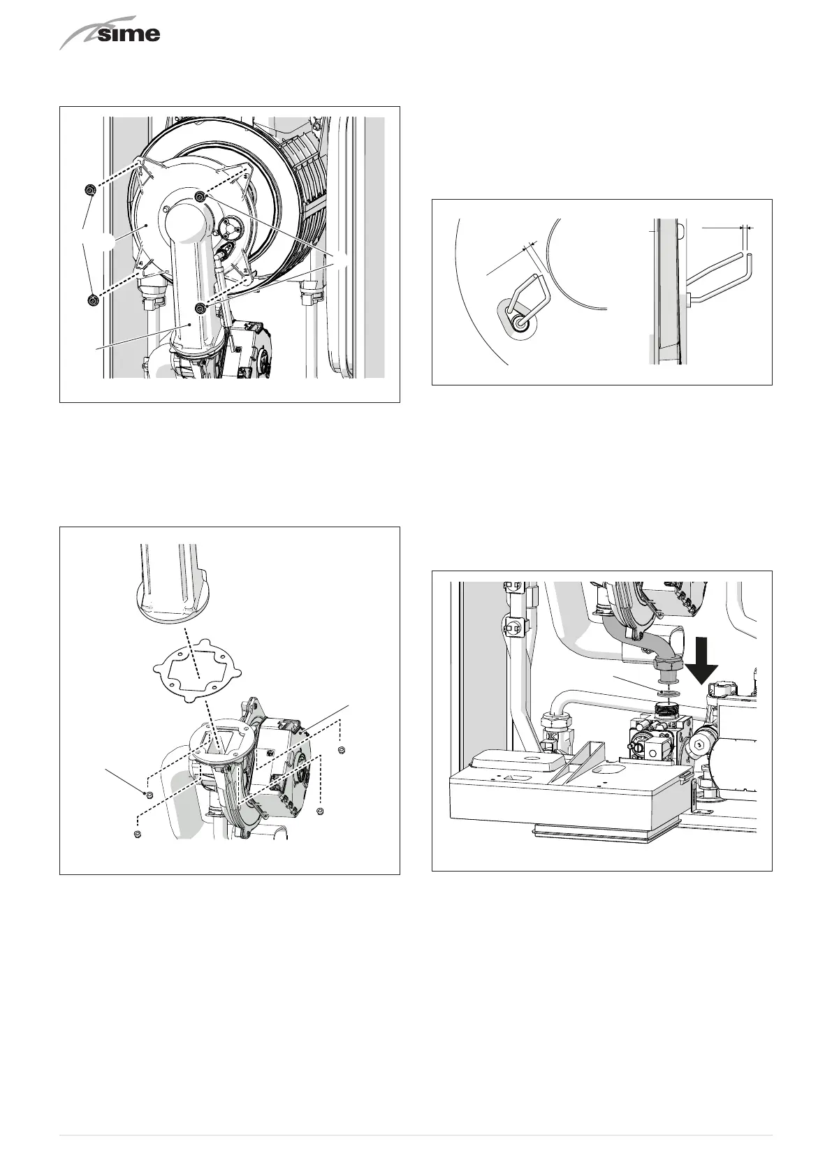
– mount the nozzle (15) back on and adjust it so that the flared
part faces downwards, as shown in the figure
15
Fig. 64
– reconnect the connections to the fan and the electrode.