32
m
CAUTION
–
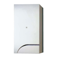
The maximum total length of the ducts
, obtained by
adding the lengths of the inlet and outlet pipes,
is determined by the load losses of the individual
accessories used and
must not exceed 15 H2O mm
.
– For all boiler versions,
the total extension
for ducts
Ø 80 mm
must not in any case exceed 25 m (inlet)
+ 25 m (outlet).
210
165
Ø 80
118
57
Ø 80
120
80
Fig. 27
6.13 Electrical connections and External con-
trols
The boiler is supplied with a mains cable. Connect the boiler
to a 230V -50Hz single phase power supply through a fused
mains switch, with at least 3 mm spacing between contacts,
fused at 3 amps.
The heating control of the boiler can be achieved by connec-
tion of either a volt free room thermostat, room thermostat/
timer or a dedicated control (listed below). For connection de-
tails see section "External timers and Room Thermostats").
If this cable needs to be replaced, an original spare must be
requested from
Sime
.
DESCRIPTION CODE
External sensor kit (ß=3435, NTC 10KOhm at 25°C) 8094101
Power cable (dedicated) 6329627
m
CAUTION
Only qualified persons in compliance with the in-
structions contained in this manual are permitted
to install, commission and maintain this boiler. The
installation of this boiler must be in accordance with
the relevant requirements of the current Gas Safe-
ty (installation and use) Regulation 1998, the local
building regulations, and I.E.E. wiring regulations.
a
WARNING
Before carrying out any interventions described:
– isolate the power supply
– isolate the gas cock
– avoid contact with any hot surfaces.
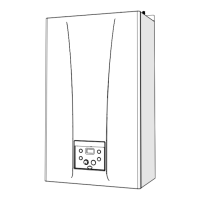
Fig. 28
To make the electrical connections:
– remove the screws (1), pull the front panel (2) forwards and
release it from the top by lifting it
2
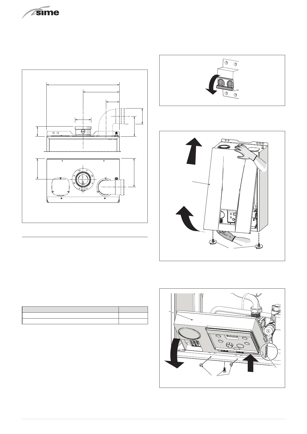
Fig. 29
– remove the screws (3) securing the control panel (4)
– move the panel (4) upwards (a) but keeping it in the side
guides (5) to the end of travel
– bring it forwards and down (b) until it is horizontal
4
b
a
5
Fig. 30