28
m
CAUTION
The boiler should be located observing the required
clearances, and provide safe, adequate service ac-
cess.
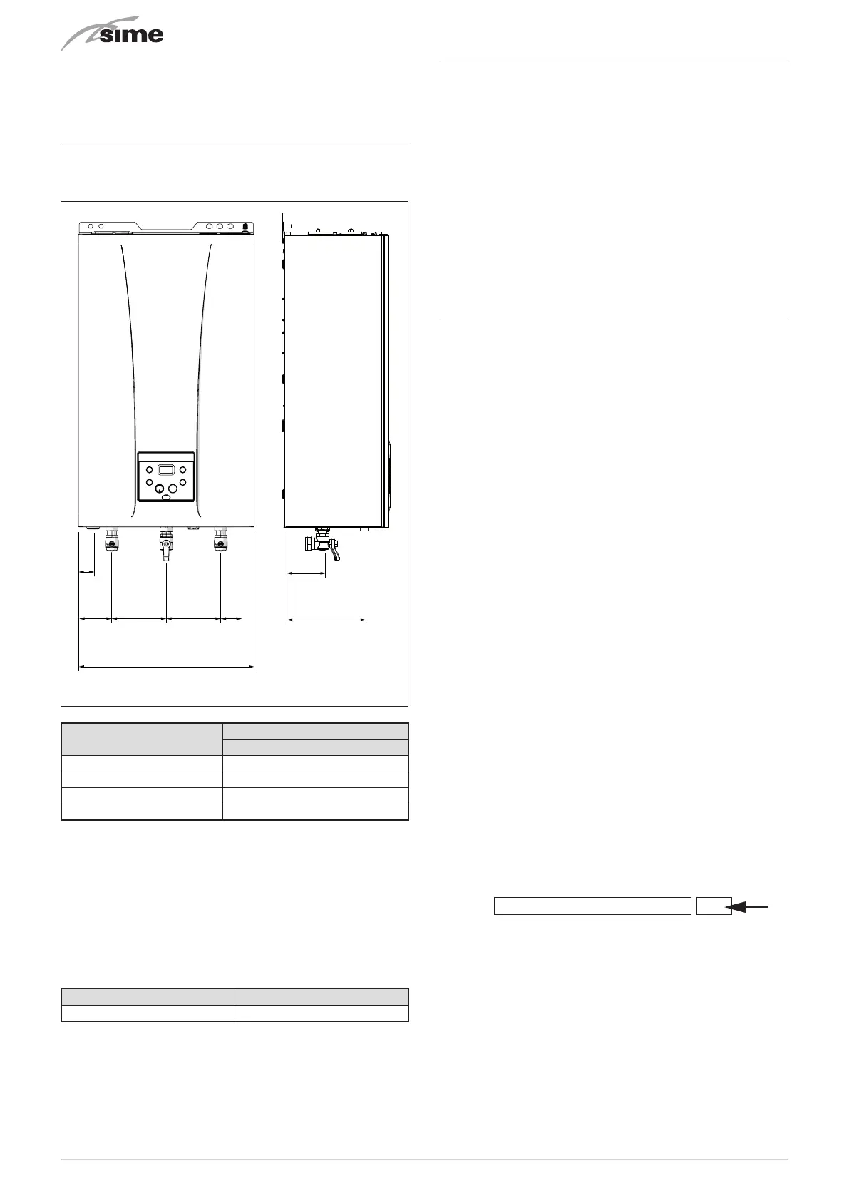
6.9 Plumbing connections
The plumbing connections have the following characteristics
and dimensions.
175
95
130 130 ==
48
420
M
Sc
Sc
G R
Fig. 22
Description
GIULIA SYSTEM
25
M - System flow Ø 22 mm
R - System return Ø 22 mm
G - Gas cock connection Ø 15 mm
Sc - Condensate outlet Ø 21.5 mm
m
CAUTION
A sealed system must only be filled by a competent
person (see section Method of filling a sealed sys-
tem page 38).
6.9.1 Plumbing accessories (optional)
To facilitate plumbing and gas connections to the systems, the
accessories as shown in the table below are available and are
to be ordered separately from the boiler.
DESCRIPTION CODE
Installation plate 8075448
NOTE:
kit instructions are supplied with the accessory itself or
are to be found on the packaging.
6.10 Condensate outlet/collection
To ensure safe disposal of the condensate produced by the
flue gases, reference should be made to BS6798:2009.
The boiler incorporates a condensate trap which has a seal of
75 mm, therefore no additional trap is required.
The condensate trap can be filled prior to the installation of
the flue by carefully pouring 1 litre of water into the exhaust
connection.
NOTE: All pipework must have a continuous fall from the boil-
er and must be resistant to corrosion by condensate, copper
or st
eel is NOT suitable. It should be noted that the connec-
tion of a condensate pipe to a drain may be subject to local
building c
ontr
ol requirements (Dealing with Condensate - see
Appendix 1).
6.11 Gas supply
GIULIA SYSTEM
boilers leave the factory configured for G20 gas
and can also work with G31 gas. It is necessary to select pa-
rameter
“01”
(see “Parameter setting and display"), set it on
the basis of the type of gas to be used and replace the nozzle
(consult the table in the “Circuit Board Replacement” para-
graph).
If changing the type of gas to be used, carry out the entire
appliance
"COMMISSIONING"
phase (page 40).
The gas connection must be made using seamless steel or
copper tube.
Where the piping has to pass through walls, a suitable insulat-
ing sleeve must be provided.
When sizing gas piping, from the meter to the boiler, take into
account both the volume flow rates (consumption) in m3/h
and the relative density of the gas in question.
The sections of the piping making up the system must be such
as to guarantee a supply of gas sufficient to cover the maxi-
mum output available from the boiler, limiting pressure loss
between the gas meter and any apparatus being used to not
greater than 1.0 mbar for family II gases (natural gas).
An adhesive data badge is sited inside the front panel; it con-
tains all the technical data identifying the boiler and the type
of gas for which the boiler is arranged.
a
WARNING
Once installation has been completed, check that
the joints are air tight as indicated in the installation
Standards.
m
CAUTION
It is recommended that the gas line has a suitable
filter.
m
CAUTION
If the gas supply is changed from G20 to G31, mark
the box on the TECHNICAL DATA PLATE.
G31 - 37 mbar