45
– measure the CO2 and verify that it corresponds to the value
appearing in the table. If not, turn the “CO
2 adjuster screw
(splitter)” (7) of the gas valve until you obtain the CO
2 value
of the table. Make any other necessary measurements.
GIULIA SYSTEM
CO2 (G20) CO2 (G31)
Qmax
(% ± 0,2)
Qmax
(% ± 0,2)
25
9,3 10,2
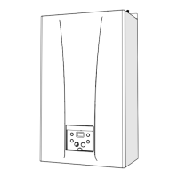
– press the button
<
to make the boiler operate at minimum
power "Lo". The message
"Lo"
will appear on the display
together with the flashing symbols
l
and
n
– measure the CO2 and verify that it matches the value shown
in the table. If not, turn the gas valve’s “CO
2 adjuster screw
to the minimum power (offset)” (8) until you obtain the CO
2
value of the table. Take any other necessary readings.
– record in Benchmark commissioning Check list (page 51).
GIULIA SYSTEM
CO2 (G20) CO2 (G31)
Qmin
(% ± 0,2)
Qmin
(% ± 0,2)
25
9,0 10,0
NOTE: There are negligeable losses of working gas pressure
attributable to the boiler as the gas cock is connected directly
to the gas valve.
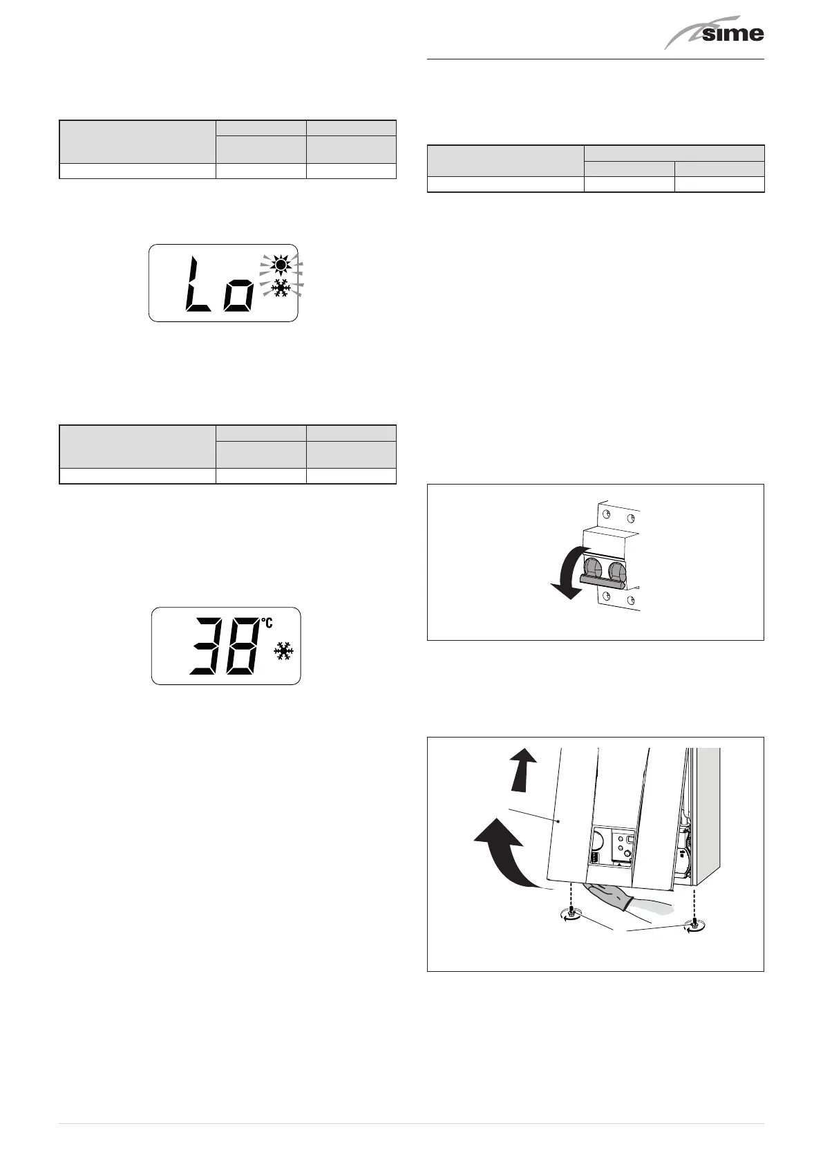
– press the button
s
to exit the "Chimney sweep Procedure”.
The boiler water delivery temperature will appear on the
display
– disconnect the pressure gauge, carefully close the pressure
point (6), test for gas tightness, put the control panel back to
the original position and refit the front panel (2). Now con-
duct a flue gas analysis as detailed in APPENDIX 2.
7.7 Gas conversion
GIULIA SYSTEM
models can be transformed from G20- to G31-
based operation by installing the “Nozzle kits for G31”, which
must be ordered separately from the boiler, and by modifying
“tS 0.1”
as indicated in the table.
GIULIA SYSTEM
G31
Kit code tS 0.1
25
(*)
5185164 2
(*) To set parameter tS 0.1 correctly, set the parameter ac-
cording to the installed model as described in the para-
graph "Lis
t of parameters".
m
CAUTION
Only qualified persons in compliance with the in-
structions contained in this manual are permitted
to install, commission and maintain this boiler. The
installation of this boiler must be in accordance with
the relevant requirements of the current Gas Safe-
ty (installation and use) Regulation 1998, the local
building regulations, and I.E.E. wiring regulations.
a
WARNING
Before carrying out any interventions described:
– isolate the power supply
– isolate the gas cock
– avoid contact with any hot surfaces.
Fig. 54
7.7.1 Preliminary operations
To carry out the conversion:
– remove the screws (1), pull the front panel (2) forwards and
release it from the top by lifting it
2
1
Fig. 55