User Manual For - CONTROLLER/DATA RECORDER MultiCon CMC-99/141
Fig. 7.50. Input channels menu – parameters specific for Hardware Output Monitor mode
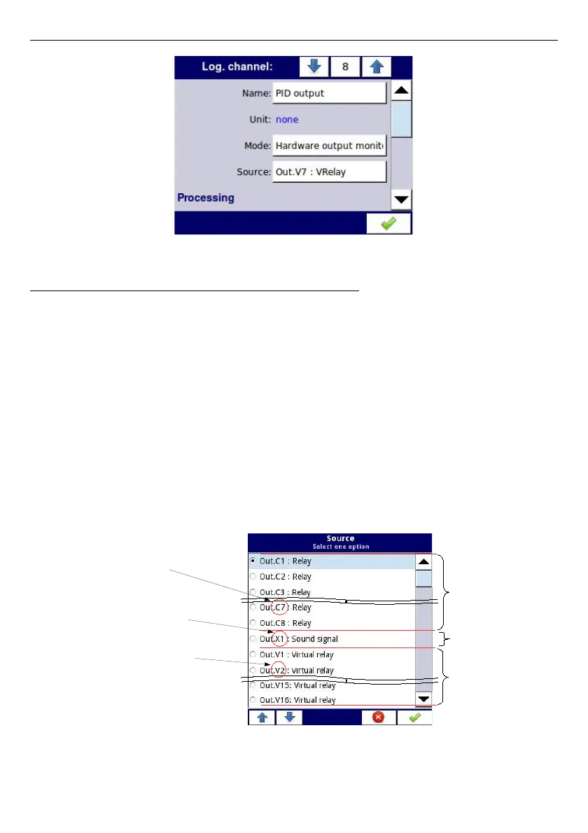
Source
parameter in the
Hardware output monitor
mode
After pressing
Source
, a list of available hardware outputs appears. The selected option will
be the source of data for that logical channel. An example list of available hardware outputs
for the device with only one output module such as
R81
- 8 relay outputs module
(see
Appendices 8.13. R45, R81, R65, R121 - RELAY MODULES
) is shown in
Fig.
7.51
.
Source
for the
Hardware output monitor
mode can be (in the same order as in the list in
the device - see
Fig.
7.51
):
– installed hardware output modules in the respective slots A, B or C (see
Fig.
4.8
)
-a list of modules currently available is on the website; more about the output
modules in
Chapter 7.10. BUILT-IN OUTPUTS
,
– built-in
Sound signal
output is always marked as
Out.X1: Sound signal
- more
about the
Sound
outputs is in
Chapter 7.10. BUILT-IN OUTPUTS
,
– built-in Virtual relays marked as Out. V1 - V16 - more about Virtual relay in Chapter
7.10. BUILT-IN OUTPUTS
.
See
Fig.
4.8
Fig. 7.51. Sample list of available hardware outputs
98
R81 module
8 relay outputs
Built-in
Sound output
Built-in
Virtual relay
Slot X (built-in slot)
Output 1
Slot V (built-in slot)
Output 2
Slot C, Output 7

 Loading...