DL100 Series Universal Low-Power Inverter
Chapter3 Inverter Wiring
3.1 Wiring precautions
(1) Make sure intermediate circuit breaker is connected between the
frequency inverter and power supply to avoid expanded accident
when the frequency inverter is faulty.
(2) In order to reduce electromagnetic interference, please connect surge
sorber on the coil of electromagnetic contactor, relay and etc. in the
surrounding circuit of the frequency inverter.
(3) Please use shielded wire of above 0.3mm² for the wiring of such
analog signals as frequency setting terminal AI and instrument loop
(AO), etc. The shielding layer shall be connected on the grounding
terminal E of the frequency inverter with wiring length less than
30m.
(4)
The stranded wire or shielded wire of above 0.75mm² shall be
selected for the wiring of input and output loop (X1-X4) of relay; and
the shielded layer shall be connected to the common port CM of
control terminals, with wiring length less than 50 m.
(5) The control wire shall be separated from the power line of major
loop;it shall be at a distance of above 10cm for parallel wiring and
vertical for cross wiring.
(6) The connecting wire between the inverter and the motor shall be less than
30m; and when it is longer than 30m, the carrier frequency of the inverter
shall be appropriately reduced.
(7) All leading wires shall be fully fastened with terminals to ensure good
contact.
(8)
The pressurization of all the leading wires shall be in compliance
with the voltage class of the frequency inverter.
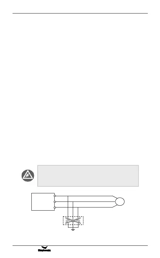
Absorption capacitor or other RC absorbers shall not be
installed at U, V and W output end of the frequency
inverter, as shown in figure 3-1.
Figure 3-1 Forbidding connecting a RC absorber at the output terminal