DL100 Series Universal Low-Power Inverter
completed through key on the operating panel.
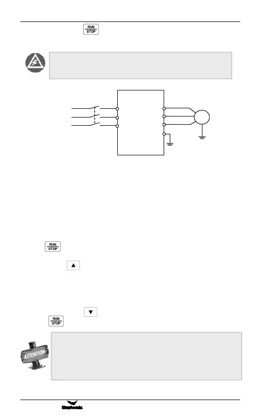
4.4.2 Simple running
Figure 4-2 Simple Running Wiring Diagram
① Connect wires as per Figure 4-2;
② Switch on the power supply after confirming that the wires are connected
correctly, and the inverter will firstly display “P.oFF” and then “0”.
③ Confirm that the frequency setting channel is at the digit setting model ([F0.00]
= 0);
④ It is required to set parameter [F2.00] and [F2.01] according to the rated nameplate
data on the inverter’s dragging motor.
⑤ Press key to start the inverter and the inverter will input 0 frequency,
displaying “0.0”.
⑥ Press Up of key to increase set frequency, and the output frequency of
the inverter will increase and the motor revolution will also increase.
⑦ Check if the motor run normally. In case of any abnormity, stop running the motor
immediately and disconnect power supply. Do not run the motor until fault cause is
found.
⑧ Press Down on the key to decrease set frequency.
⑨ Press key again to stop running and cut off the power supply.
It is absolutely forbidden to connect the power cord to the
output U, V, W of the frequency inverter.
Three-phase circuit
breaker
The default value of the carrier frequency is fixed (2-8 KHz). If the
motor is completely empty-load, slight oscillation may occur sometimes
in the operation under high carrier frequency. At this time, please reduce
the setting valueof the carrier frequency. (Parameter [F0.08]).