DL100 Series Universal Low-Power Inverter
3.5 Wiring of control loop terminal
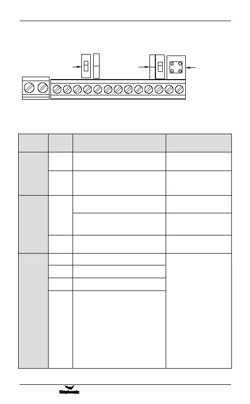
(1) Diagram of control loop terminal
(2) Function description of control loop terminal
Externally providing +10V
(0~10mA) power supply
External providing +24V
(0~50mA) power supply
(CM terminal is the power grand).
Voltage signal input terminal
(when the toggle switch is set to V)
Current signal input terminal
(when the toggle switch is set to
A)
Analog input signal common
terminal (VS power ground)
Multifunctional input terminal 1
The function of the
multi-function input
terminal is set by the
parameters [F3.01] ~
[F3.04], and it is
effective when closed; in
the logic selection of the
input terminal, when the
toggle switch is turned to
L, the terminal and CM
are closed and effective,
and when the switch is to
H, the terminal is
connected to 24V End
closure effective.
Multifunctional input terminal 2
Multifunctional input terminal 3
Multifunctional input terminal 4
TA TC X1 X2 X3 X4 OC CM 24V VS AI AO GND RS+ RS-
VCC
GND
RS-
便捷485
通讯接口
电压/电流输
入拨动端子
A
V
输入端子
逻辑选择
H
L
RS+
Input terminals are
selected logically
Voltage/current
input toggle
terminaly
Convenient 485
communication
interface