DL100 Series Universal Low-Power Inverter
Detailed Description of Functions 45
6.5 Digital output and swing frequency operation parameter group
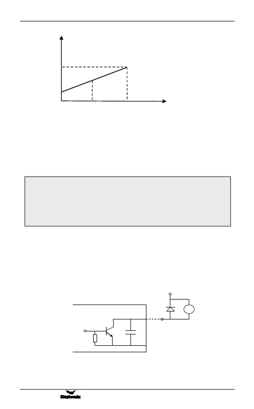
It is used to define the content represented by the open collector output terminal
OC and the relay output contact. The internal wiring diagram of the open-collector
output terminal is shown in Figure 6-12. When the setting function is valid, the
output is low, and when the function is invalid, the output is in a high-impedance
state.
Relay contact output: When the set output function is valid, the normally open
contact TA-TC is turned on.
Figure 6-11 Analog output content of analog output
terminal
F4.00 Output terminal OC function selection
Predetermined area
:
0 ~ 15
F4.01 Relay output TA/TC function selection
Predetermined area
:
0 ~ 15
Figure 6-12 Internal wiring of OC output terminal
Output frequency
Output current
Output voltage
Upper limit frequency
Maximum/rated voltage