DL100 Series Universal Low-Power Inverter
3.2 Wiring of peripheral elements
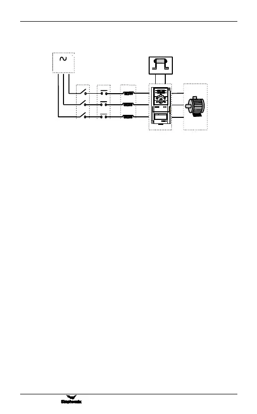
Power supply
The inverter shall be provided with power in accordance with specification
of input power supply designated by this operating manual
Air switch
1) When the frequency inverter is maintained or not in use for a long time,
2) the air switch will separate the frequency inverter from the power
supply;
3) When the input side of the frequency inverter has failures like short
circuit, the air switch can provide protection.
Contactor
It can conveniently control power-supply and power disconnection of the
inverter, and the power-on and power-off of the motor.
AC reactor
1) To promote power factor;
2) To reduce harmonic input of the inverter against the grid;
3) Weaken influenced caused by unbalanced voltage of three-phase power
supply.
Brake resistance
When the motor is at the dynamic braking status, it can avoid producing over
high pumping voltage in the DC loop.
Figure 3-2 Inverter Wiring
WARNING
1.Refer to the instruction manual before installation
3.Do not remove any cover while applying power
and at least 10min. after disconnecting power.
4.Securely ground(earth) the equipment.
2.Do not connect AC power to output terminals UVW.
and operation.
!
E550
Air switch Contactor AC reactor