DL100 Series Universal Low-Power Inverter
Detailed Description of Functions 27
Chapter6 Detailed Description of Functions
6.1 Basic operating parameter group
It is used to select the setting channel/mode of the inverter's operating
frequency.
0: Digital setting
The set frequency of the inverter is set by the parameter [F0.01].
1: External analog
The operating frequency is set by the external input voltage signal (0~10V) or
current signal (0~20mA). For related characteristics, refer to the description of the
parameters [F3.09] and [F3.10].
2: External communication
Receive the frequency setting command of the upper computer or the host
computer through the serial RS485 interface.
3: Panel potentiometer
The operating frequency is set by the potentiometer on the operation panel.
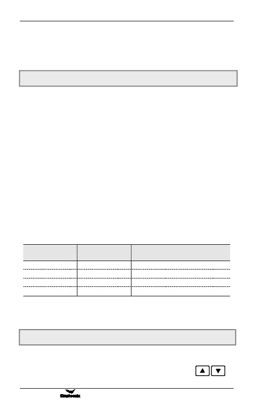
4: External terminal selection
Determine the frequency input channel through the external multi-function
terminal (the selection of the function terminal is determined by the parameters
[F3.01] ~ [F3.04]).
Frequency setting
Channel selection 2
Frequency setting
Channel selection 1
Frequency setting channel
External input signal(0~10V/0~20mA)
Note: When the terminal and CM are closed, it is 1.
5: Combination settings
It is selected by [F0.12] group parameters.
When the frequency input channel selects the digital setting ([F0.00] = 0), the
output frequency of the inverter is determined by this value. When the operation
panel is in the normal monitoring mode, you can directly press the
key to modify this parameter.
F0.00 Frequency input channel/mode selection Setting range: 0 ~ 5
F0.01 Frequency digital setting Setting range: 0.00 Hz ~ upper limit
frequency