DL100 Series Universal Low-Power Inverter
44 Detailed Description of Functions
Select the meaning of analog output terminal AO (set in digit decimal system)
LED units: define the meaning of analog output AO
0: Output frequency
The amplitude of the analog output (AO) is proportional to the output frequency
of the inverter. The set upper limit of analog output ([F3.18]) corresponds to the
upper limit frequency.
1: Output current
The amplitude of the analog output (AO) is proportional to the output current of
the inverter. The set upper limit of analog output ([F3.18]) corresponds to twice
the rated current of the inverter.
2: The output voltage
The amplitude of the analog output (AO) is proportional to the output voltage of
the inverter. The set upper limit of analog output ( [F3.18]) corresponds to the
basic output voltage [F2.01].
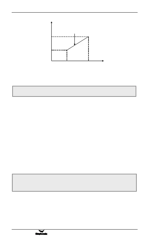
Define the maximum and minimum values of the analog output AO output
signal. As shown in Figure 6-11:
F3.16 Analog output selection Predetermined area
:
0 ~ 2
F3.17 AO output lower limit Predetermined area
:
0.00 V ~ [F3.18]
F3.18 AO output upper limit Predetermined area
:
[F3.17] ~ 10.00 V
Figure 6-10 Diagram of the corresponding relationship
between analog input and set frequency
频率
[F1.00]
[F1.04]
[F1.03]
输出频率
[F1.01]
电压