5 Connecting the field wiring and AC power
This chapter describes connecting field wiring for all devices, smoke detectors, releasing appliances, abort switches, and so on, to the
4004R, and wiring AC power to the panel.
Before installing any equipment, always make a survey of the area to be covered. Also, be sure to follow the requirements of applicable
codes and standards, as well as the directives of Authorities Having Jurisdiction (AHJs).
Remove the plastic PCB cover as described in Removing the plastic PCB cover in the previous chapter.
5.1 Wiring Initiating Device Circuits
IDCs are used for wiring smoke and heat detectors to the 4004R. Be aware that correct operation of the 4004R depends on the proper
installation and placement of smoke and heat detectors. This is particularly true when installing a cross-zoned, agent release system.
Cross-zoning requires the operation of two zones to confirm the alarm and initiate the releasing function.
With a cross-zoned system, the detectors in the room must be installed so that each successive detector in the space being protected is
on an alternating zone pattern. Ensure that there are at least two detectors in each protected space, and reduce the detector installation
spacing to 0.7 the linear spacing. The location and spacing of detectors shall be in accordance with the requirements of Section 5.7.3 of
the National Fire Alarm Code (NFPA 72), 2002 Edition.
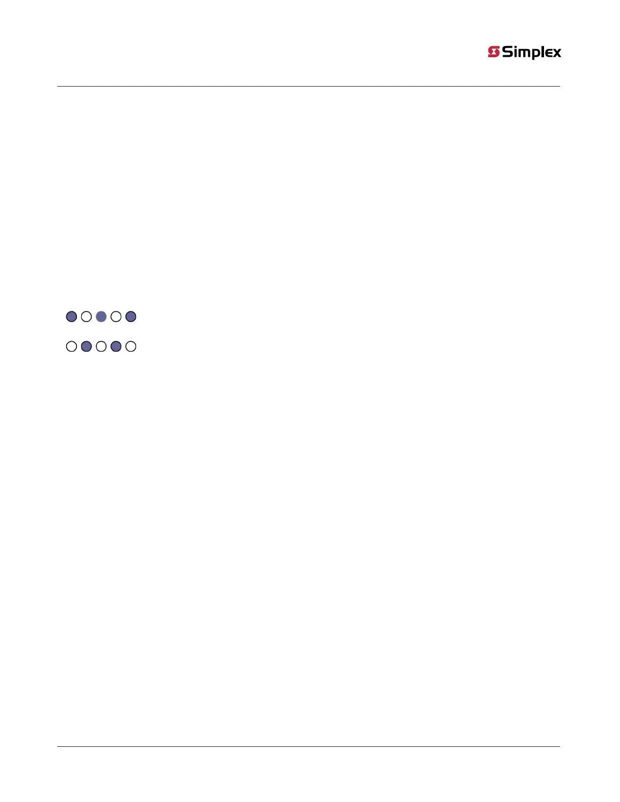
In the following example, the shaded detectors are on Zone 1 and the non-shaded detectors are on Zone 2.
Figure 11: Detector zones example
Adhere to the following guidelines when wiring IDCs:
• All wiring must be from 12 AWG maximum to 18 AWG minimum.
• Conductors must test free of all grounds.
• All wiring is supervised and power limited.
• Leave 3.3K, 1/2W resistor (378-115) across all unused IDC terminals. See note 4 in Figure 12 (two-wire) or note 4 in Figure 13(four-wire).
• Terminate Style B (Class B) circuits with a listed 3.3K, 1W (Simplex Part Number 733-893) end-of-line resistor. See note 5 in Figure 12
(two-wire) or note 5 in Figure 13 (four-wire).
• Terminate Style D (Class A) circuits with a listed 3.3K, 1 W (Simplex Part Number 733-893) end-of-line resistor. See note 6 in Figure 12
(two-wire/Class A) or note 6 in Figure 13 (four-wire/Class A).
• For Canadian applications, use ULC listed end-of-line resistors 2081-9010C, 2081-9018, or 2081-9037C.
• The maximum line resistance for a circuit is 50 Ohms.
• The maximum number of Simplex smoke/heat detectors on an IDC is 30. The maximum number of Thorn Smoke detectors is 30, the
maximum number of Thorn heat detectors is 20.
• The maximum detector standby current is 3mA.
• Voltage rating – nominal 24 VDC, 0.5V peak-to-peak ripple maximum.
• For all applications, the maximum voltage (open circuit) is 28 VDC. Maximum current is 75mA.
• Any combination of the below Simplex detectors and bases may be installed, except only one model 4098-9683 may be used on a
circuit. The compatibility identifier is the model number found on the detector, base, and control unit.
• When programmed for preaction/deluge applications, 5 through 8, a short circuit alarm results in causing a manual release within a
maximum of 30 seconds. The 4098-9682, Four-Wire Base, is prohibited from being used if Applications 5, 6, 7, or 8 are programmed.
See note 8 in Figure 12 (two-wire) or note 7 in Figure 13(four-wire).
• When IDC wiring is routed outside the building, use Listed Secondary Protector 2081-9044 or 2081-9028. A protector must be installed
at the building entrance such that protected wiring is segregated from unprotected outdoor wiring.
• Refer to document 579-832 for the 2-Wire Detector Compatibility Chart.
• Compatible Simplex devices. Refer to Simplex document 574-709, Detectors, Sensors, and Bases application manual, for installation
instructions.
4098-9601, Photoelectric Smoke (2.8 %) Detector
4098-9602, Combination Photoelectric/Heat Detector
4908-9603, Ionization Smoke Detector
4098-9605, Photoelectric Smoke (3.5%) Detector
4098-9612, 135˚ Fixed Temperature Electronic Heat Detector
4098-9613, 135˚ Fixed Temperature with Rate-of-Rise Electronic Heat Detector
4098-9614, 200˚ Fixed Temperature Electronic Heat Detector
4098-9615, 200˚ Fixed Temperature with Rate-of-Rise Electronic Heat Detector
Also compatible with contact closure devices.
• Compatible Simplex Bases. Refer to Simplex Part Number 574-706, 4098-9788 Smoke Detector Base installation instructions.
page 18 579-354 Rev. X
4004R Fire Alarm installation, programming, and operating instructions