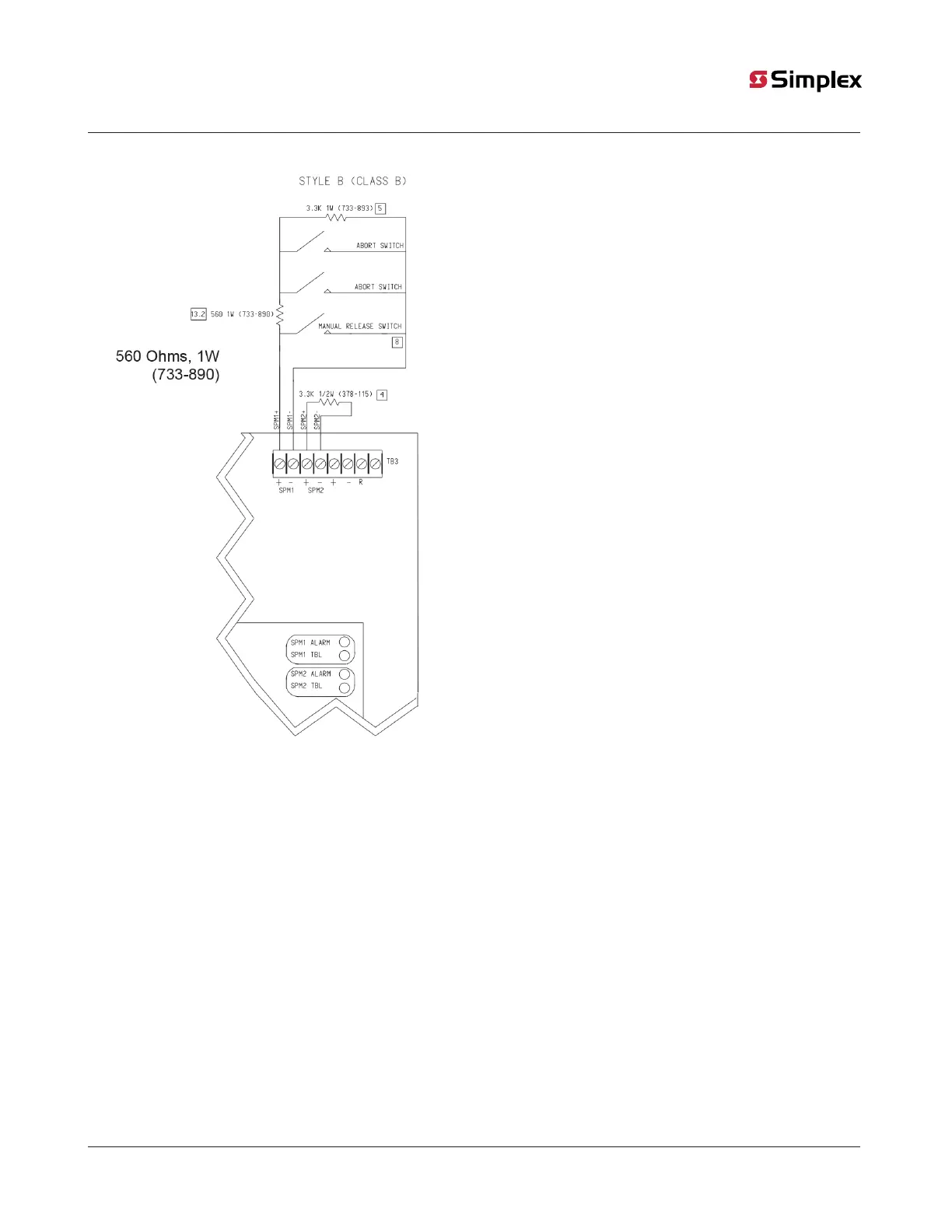
Figure 18: SPM field wiring connections Note:
Connect abort switches and manual release stations
as shown in the figure. When using external current-
limiting resistors, the special purpose monitoring
circuits cannot be wired Style D and must only be
wired Class B.
The series current-limiting resistor shall be terminated
and enclosed inside the mounting box of the first
abort switch.
5.3.3 Wiring shared Abort/Manual Release with an internal current limiting resistor
Adhere to Figure 19 and the following guidelines when wiring SPM circuits with internally current-limited abort switches;
• The + connection from the SPM is made to the lead of the factory-installed, current limiting resistor. As shown in Figure 19, the –
connection is made to the open terminal. The terminal that is connected to the current limiting resistor must not be tampered with.
• Use only manual release and abort switches that are UL Listed for fire use.
• Connect the manual release switch between the last abort switch and the end-of-line resistor. See Figure 20.
• Use only UL Listed abort switches that are listed with an internal resistance of 1.2 K Ohms.
• No more than five abort switches are to be connected to the same circuit.
• All wiring must be 12 AWG maximum to 18 AWG minimum.
• Conductors must test free of all grounds.
• All wiring is supervised and power limited.
• Leave 3.3 K, 1/2 W (378-115) resistor across all unused SPM terminals. See item 4 in Figure 20.
• Terminate Style B (Class B) circuits with a listed 3.3K, 1W (Simplex Part Number 733-893) end-of-line resistor. See item 5 in Figure 20.
• For Canadian applications, use ULC-listed end-of-line resistors 2081-9010C, 2081-9018, or 2081-9037C.
• Terminate Style D (Class A) circuits with a listed 3.3K, 1 W (Simplex Part Number 733-893) end-of-line resistor. See item 6 in Figure 20.
• Maximum line resistance is 50 Ohms.
• Normal condition (no devices closed). Current at 24 VDC: 6.0 mA
• Manual Release condition. Current at 24 VDC: 25 mA
• SPM circuits do not support the connection of smoke or heat detectors.
• When SPM wiring is routed outside the building, use Listed Secondary Protector 2081-9044 or 2081-9028. A protector must be
installed at the building entrance such that protected wiring is segregated from unprotected (outdoor) wiring.
page 26 579-354 Rev. X
4004R Fire Alarm installation, programming, and operating instructions