9 - 13
PEERLESS (GEAR DRIVE) MODELS
Foot Pedal Assembly Removal &
Installation
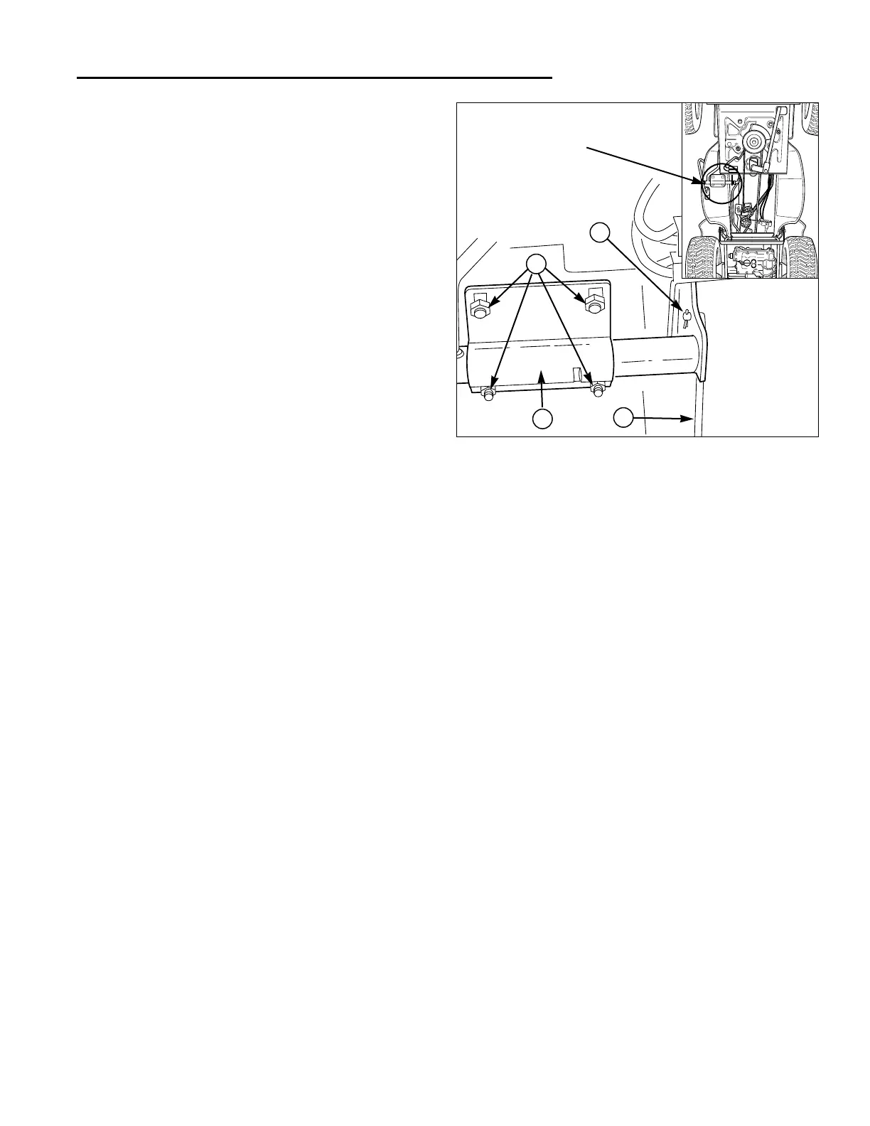
Refer to Figure 12.
1. Park the tractor on a flat level surface, such as a con-
crete floor, and block the wheels. Do not engage the
parking brake.
2. Remove the mower deck.
3. Remove the rubber pad from the brake pedal by
twisting and pulling the pad.
4. Remove the cotter pin and washer (D) from the brake
rod (A) and disconnect the brake rod (A) from the
brake pedal arm.
5. Remove the 4 nylock nuts (C) securing the tube
clamp (B). Push on the top of the foot rest pad to
hold the carriage bolts in place.
6. Remove the tube clamp (B).
7. Remove the pedal assembly.
Install in reverse order of removal. After installation, per-
form BRAKE & BRAKE SPRING ADJUSTMENT proce-
dures in Section 4.
Clutch / Brake Linkage
Removal and Installation
Refer to Figure 11.
PARKING BRAKE ROD
1. Park the tractor on a flat level surface, such as a con-
crete floor, and block the wheels. Do not engage the
parking brake.
2. Remove the parking brake knob (H, Figure 11).
3. Remove the brake return spring (G).
4. Elevate the front end (see ELEVATING FRONT END
FOR SAFE SERVICE, Section 6).
5. Slide the parking brake rod (F) out the parking brake
lever (D) and out the bottom of the tractor.
Install in reverse order of removal.
FRONT BRAKE ROD
1. Park the tractor on a flat level surface, such as a con-
crete floor, and block the wheels. Do not engage the
parking brake.
2. Remove the brake return spring (G, Figure 11).
3. Remove the idler assembly spring (N).
4. Remove the cotter pin and washer (A) from the front
and back of the front brake rod (B).
5. Remove the front brake rod (B).
Install in reverse order of removal.
9 Drive Controls Service
Peerless (Gear Drive) Models
Figure 12. Disconnect Brake and Transmission
A. Brake Rod C. Nylock Nuts
B. Tube Clamp D. Cotter Pin & Washer
B
C
A
Area of
Detail
REAR BRAKE ROD
1. Park the tractor on a flat level surface, such as a con-
crete floor, and block the wheels. Do not engage the
parking brake.
2. Remove the brake return spring (G, Figure 11).
3. Remove the idler assembly spring (N).
4. Disconnect the brake return spring (I) from the frame
and brake rod (K).
5. Remove the locknut (X) and spring (W) from the front
of the rear brake rod (K).
6. Remove the cotter pin and washer (A) from the rear
of the rear brake rod (K).
7. Remove the brake rod (K).
Install in reverse order of removal. After installation, per-
form BRAKE & BRAKE SPRING ADJUSTMENT proce-
dures in Section 4.
IDLER ASSEMBLY
1. Park the tractor on a flat level surface, such as a con-
crete floor, and block the wheels. Do not engage the
parking brake.
2. Remove the front brake rod (B), rear brake rod (K),
and parking brake rod (F) (see previous procedures).
3. Remove the capscrew (T) securing the idler assem-
bly (V) to the frame pivot.
Install in reverse order of removal. After installation, per-
form BRAKE & BRAKE SPRING ADJUSTMENT proce-
dures in Section 4.
D
 Loading...