7 Electrical System Service
Component Location & Replacement
7 - 16
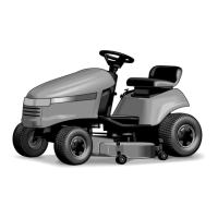
Seat Switch
See Figure 5
1. Disconnect and secure the negative battery cable.
See DISCONNECTING THE BATTERY CABLES,
Section 6.
2. Remove the seat and slide assembly from the hinge
plate, and separate the seat pan from the slide
assembly (see SEAT REMOVAL, Section 13).
3. Disconnect the wire harness from the seat switch.
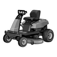
4. Push in the three outer tabs (A, Figure 6) and rotate
the switch assembly counterclockwise. The outer
locking tabs (A) will break when pushed in.
5. Remove the switch assembly from the seat pan.
6. Install a new switch in the seat pan. Turn the switch
assembly clockwise to lock into place.
7. Reconnect the wire harness.
Battery
See Figure 5.
Refer to REMOVING AND INSTALLING THE BATTERY,
Section 6.
Figure 5. Seat Switch and Battery
Battery
Seat Switch
Figure 6. Seat Switch Removal
A. Outer Locking Tabs
A
A
A
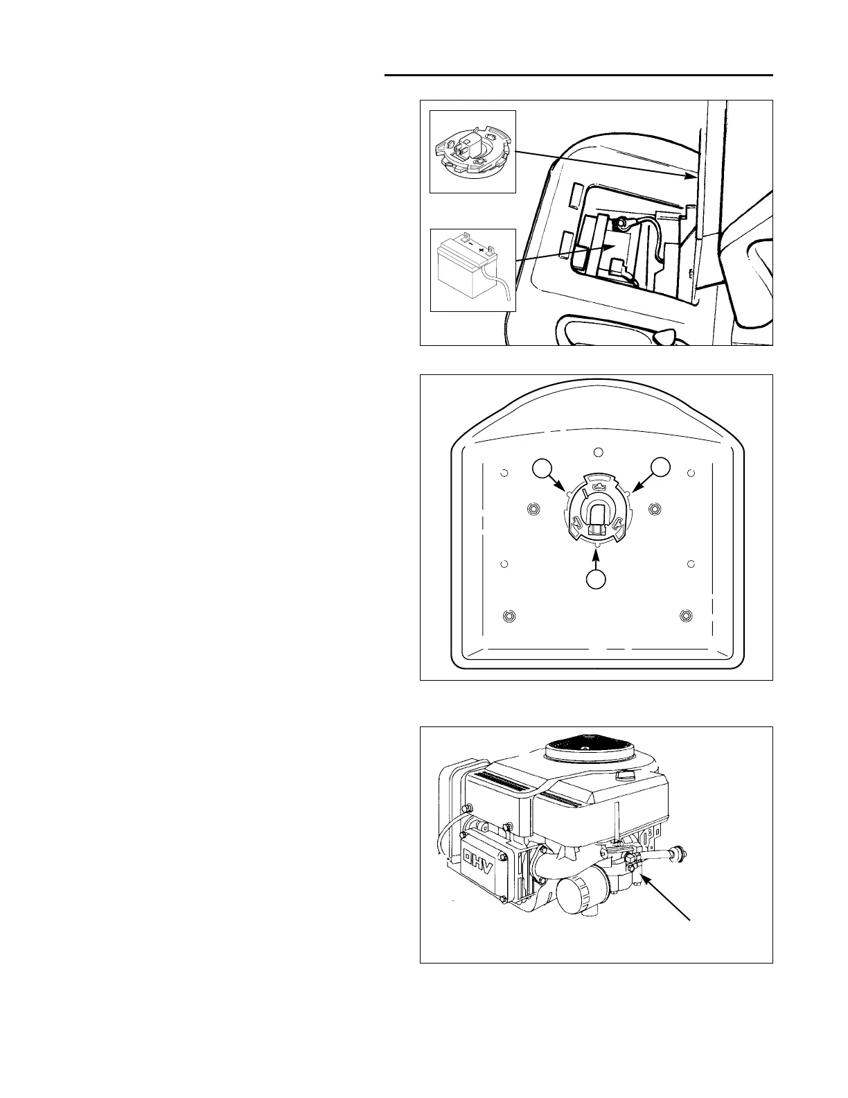
Fuel Solenoid
See Figure 7.
Refer to the engine manufacturer's manual for specific
information regarding engine component testing and
replacement.
A general testing procedure for the fuel solenoid is pro-
vided in the COMPONENT TEST section.
Ignition Coil (Magneto)
Located under the engine air shroud.
Refer to the engine manufacturer's manual for specific
information regarding engine component testing and
replacement.
Figure 7. Fuel Solenoid Location
Fuel
Solenoid