11 Transmission Teardown
Hydro-Gear 0500 / 0650
11 - 22
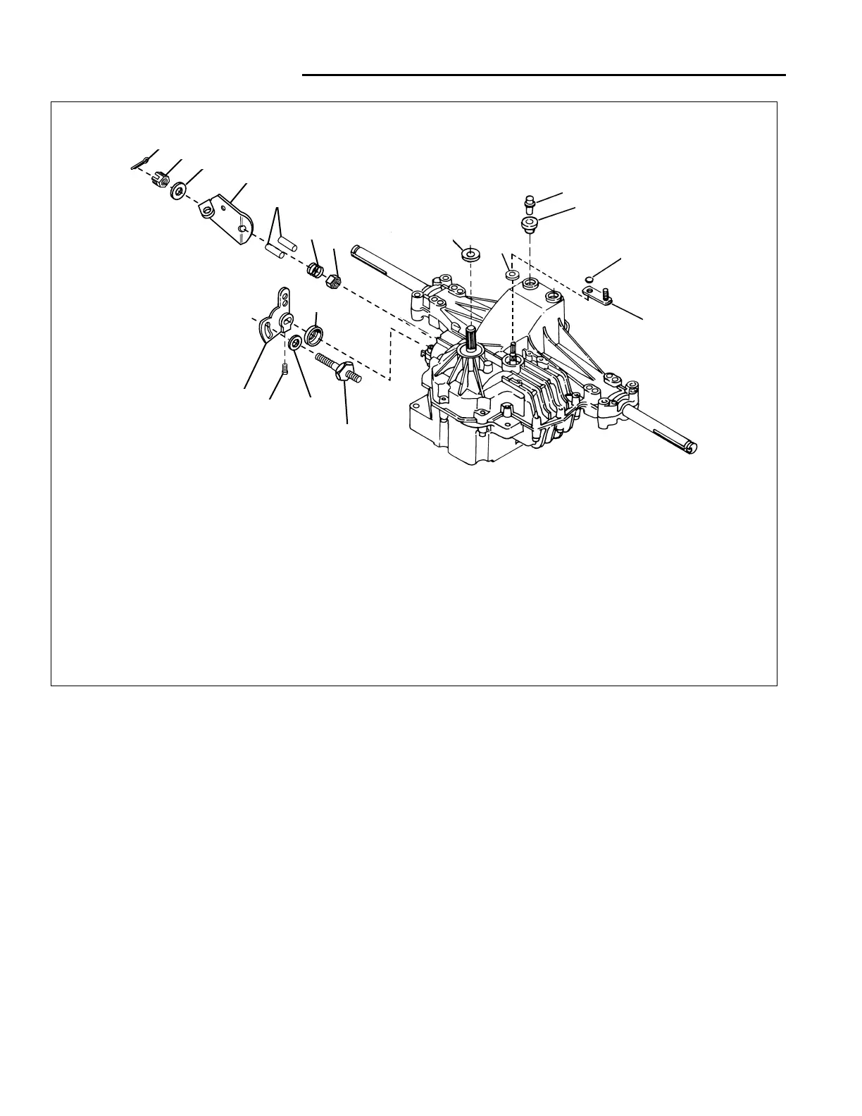
Install External Control Linkage
BRAKE ARM
1. Install the brake retaining nut (Ref 9, Figure 38).
2. Torque the retaining nut on the brake nut to 120–185
in-lbs.
3. Lubricate and install the actuator pins (Ref 6) into the
case.
4. Install the spring (Ref 17), brake arm (Ref 7), washer
(Ref 8), castilated nut (Ref 13), cotter pin (Ref 18).
Do not tighten the castilated nut (Ref 13) at this time.
NOTE: Two versions of the brake retainer nuts have
been used. Early production employed “Nylock” type
nuts, while later production used a castellated nut with a
cotter pin for retainment. Regardless of the type of nuts
used, the adjustment procedure is the same.
1
12
2
14
17
9
6
7
8
13
18
16
10
11
3
5
15
4
1 1 BREATHER ASSY.
2 1 BUSHING, Rubber
3 1 ARM, Bypass
4 1 SEAL
5 1 SET SCREW
6 2 ACTUATOR PIN
7 1 ARM, Brake
8 3 WASHER, 7/16 x 7/8 x 1/16
9 2 NUT, Hex, Lock, 5/16 x 24
10 1 SEAL, Lip
11 1 SEAL, Lip
12 1 RING, Retaining
13 1 CASTLE NUT, 5/16-24
14 2 PUCK, Dampener
15 1 ARM, Control
16 1 STUD, 5/16-24
17 1 SPRING, Helical Compression
18 1 COTTER PIN
Ref. Qty. Description Ref. Qty. Description
Figure 38. Brake and Transmission Control Linkages
5. The parking brake was initially set at a specific run-
ning clearance of .025” to .030” between the two
outer stators. To check the clearance of the brakes in
your transaxle, rotate the brake lever until it contacts
the case (fully off position). Place a feeler gage
between the two outer stators. If the clearance is not
correct, make the necessary change with the brake
adjustment nut.
6. Install brake bolt cotter pin if equipped. Lubricate
brake stators with spray lubricant.
TRANSMISSION CONTROL ARM
1. Install the stud (Ref 16, Figure 38) in the transmission
casing.
2. Install the dampener puck (Ref 14) on the stud.
3. Install the control arm (Ref 15) on the control shaft
and secure with a set screw (Ref 15). Coat the set
screw (Ref 5) with thread locking solution before
installing.
 Loading...