7 Electrical System Service
Circuit Breaker / Key Switch
7 - 24
D. Circuit Breaker Test
The circuit breaker is connected to one of the large posts
of the solenoid along with the positive battery cable.
1. Set the VOM to VDC.
2. With the negative probe, touch ground.
3. Touch the positive probe to one post of the circuit
breaker, and then the other. Both posts should have
close to full battery voltage going to them. If not,
replace the breaker.
4. Set VOM to Ohms.
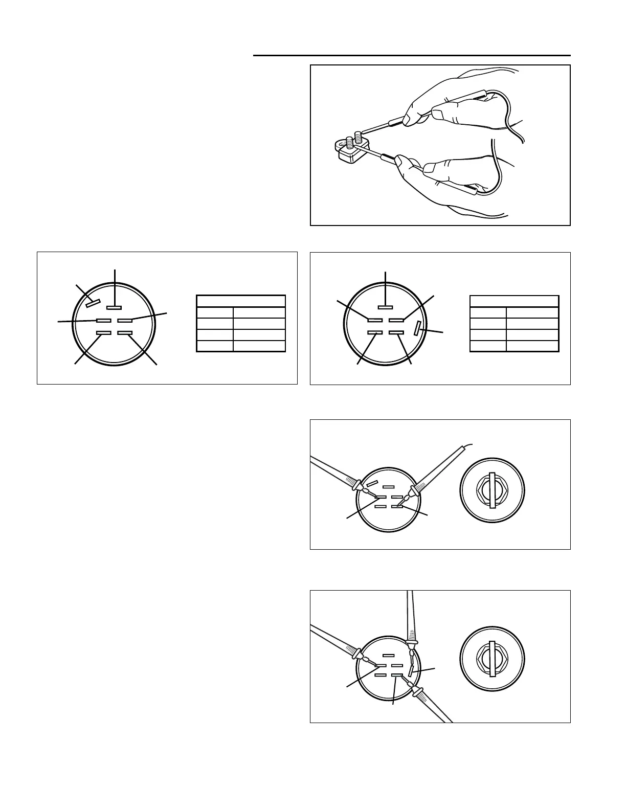
5. See Figure 12. Disconnect the circuit breaker leads
and probe both circuit breaker terminals. If the VOM
reads 5 Ohms or more, replace the circuit breaker.
Figure 12. Testing the Circuit Breaker
E. Key Switch Tests
At the time of this printing two key switches have been
used in Regent / 500 / 2500 series tractors.
Early Models–with Briggs & Stratton engines: Hydro-
Gear 0500 / 0650 models, and Peerless models pro-
duced before model year 1998 use the key switch pic-
tured in Figure 13.
Later Models–with Kohler engines: Tuff Torq K-56 mod-
els, and Peerless models (1998 and later) use the key
switch pictured in Figure 14.
TEST OFF POSITION
1. Remove the plug from the ignition switch.
2. Remove the ignition switch from the control panel.
3. Set VOM to Ohms.
4. Early Models–See Figure 15. With the key switch in
the OFF position connect test leads to terminals G
and M. The VOM should show continuity.
Later Models–See Figure 16. With the key switch in
the OFF position connect test leads to the following
terminal combinations: G to M, G to A, and M to A.
The VOM should show continuity for these three
combinations.
5. Check all other connection combinations for NO con-
tinuity. The combinations tested in step 4 should be
the only combinations that have continuity; all other
connection combinations should have NO continuity.
 Loading...