7 - 27
7 Electrical System Service
Foot Pedal / Transmission Switch
G. Foot Pedal Switch Tests
Regent / 500 / 2500 series tractors use two foot pedal
interlock switches (one gray, one black) activated by the
by the brake pedal.
The gray switch is normally closed, meaning that when
the brake pedal is at rest (up, not depressed) the switch
is closed and will conduct current. Depressing the brake
pedal (or switch plunger) opens the switch.
The black switch is normally open, meaning that when
the brake pedal is at rest (up, not depressed) the switch
is open and will not conduct current. Depressing the
brake pedal (or switch plunger closes the switch.
GREY SWITCH TESTS
1. Pull the wire harness off the back of the switch.
2. Set VOM to Ohms. With the brake pedal up (not
depressed) probe the switch terminals. The VOM
should show continuity.
3. Depress the brake pedal and engage the parking
brake.
4. Probe the switch terminals. The VOM should show
no continuity.
BLACK SWITCH TESTS
1. Pull the wire harness off the back of the switch.
2. Set VOM to Ohms. With the brake pedal up (not
depressed) probe the switch terminals. The VOM
should show no continuity.
3. Depress the brake pedal and engage the parking
brake.
4. Probe the switch terminals. The VOM should show
continuity.
Replace a switch that does not pass all tests.
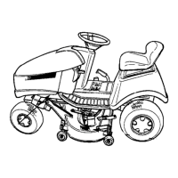
Figure 24. Foot Pedal Switch -
Pedal / Plunger Not Depressed
Gray Switch: Continuity
Black Switch: No Continuity
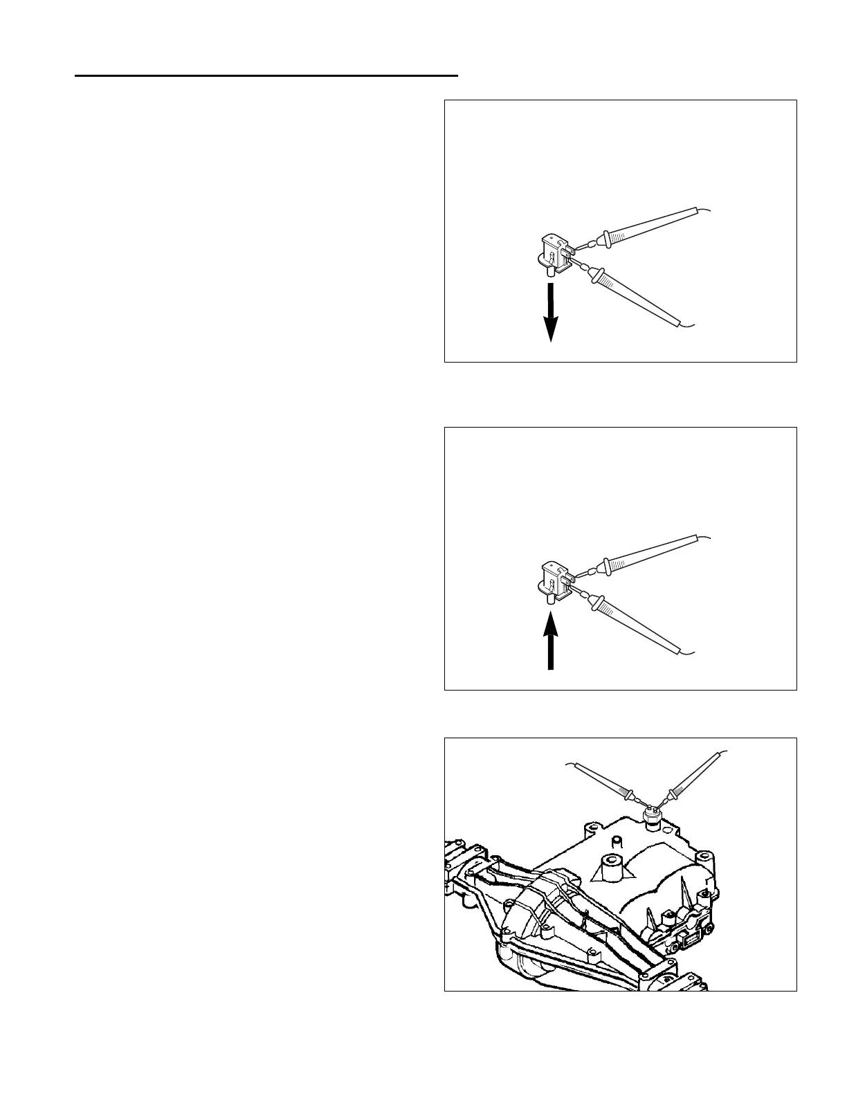
Figure 25. Foot Pedal Switch -
Pedal / Plunger Depressed
Gray Switch: No Continuity
Black Switch: Continuity
H. Transmission Switch Tests
(Peerless Models Only)
Peerless gear drive model Regent / 500 / 2500 series
tractors use a neutral safety switch that screws into the
transmission case. The switch is normally closed, mean-
ing that when the transmission is in NEUTRAL the switch
is closed and will conduct current. Placing the ground
speed control lever in gear opens the switch.
TEST NEUTRAL SAFETY SWITCH
1. Remove the wire harness plug from the safety switch.
2. Set VOM to Ohms. With the transmission in NEU-
TRAL probe the switch terminals. The VOM should
show continuity.
3. Place the ground speed control lever in first gear.
4. Probe the switch terminals. The VOM should show
no continuity.
Replace a switch that does not pass all tests.
Figure 26. Test Transmission Switch
 Loading...