7 - 23
7 Transmission Repair
7B Eaton 750 / 751
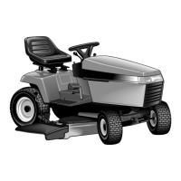
Figure B–49. Remove Control Shaft and Insert
10. Remove the control shaft and insert from the housing
and cam ring assembly.
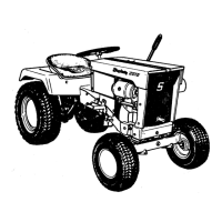
Figure B–50. Remove Insert From Control Shaft
11. Remove the cam ring insert from the control shaft.
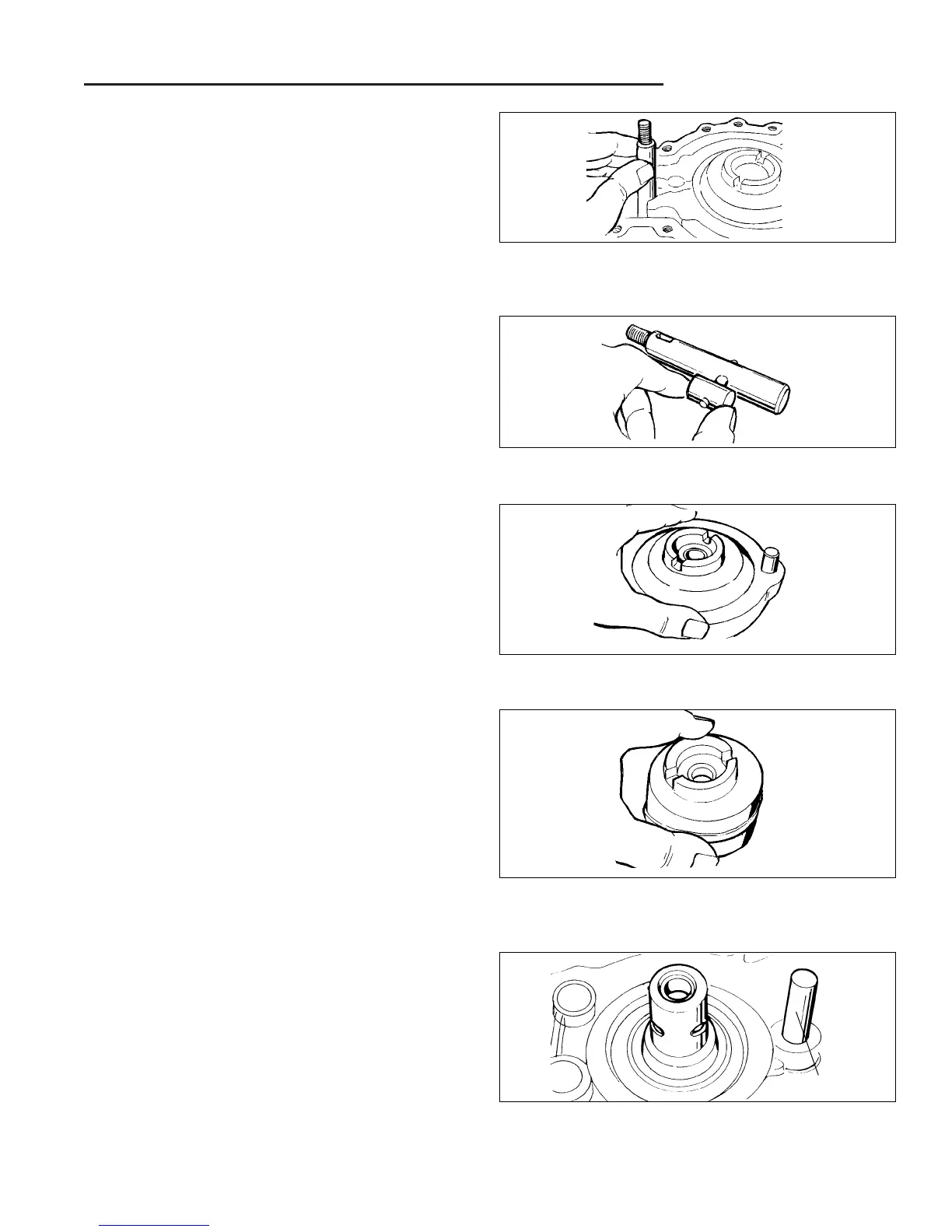
Figure B–51. Remove Cam Ring Assembly
NOTE: It is essential that the pump rotor assembly
remain intact during handling as each ball piston is
matched to its respective bore.
12. Install a wide rubber band around the pump rotor to
retain the ball piston in their bores. Remove the cam
ring assembly from the housing.
Figure B–52. Remove Pump Rotor Assembly
13. Carefully remove the pump rotor assembly from the
housing, making sure the ball pistons are not dis-
lodged from their bores.
14. Set the pump rotor aside for inspection.
Figure B–53. Inspect Pump and Motor Journals
15. The pump and motor journals and cam ring dowel
cannot be removed once they have been installed in
the housing assembly.
NOTE: Inspect the pump and motor journals for any
irregularities. If any are found, the housing must be
replaced as a complete assembly.
16. In most cases, we do not recommend removal of the
dampening pistons for inspection or cleaning. Normal
flushing should be all that is required for cleaning.
Cam Ring Dowel