7 - 37
7 Transmission Repair
7B Eaton 750 / 751
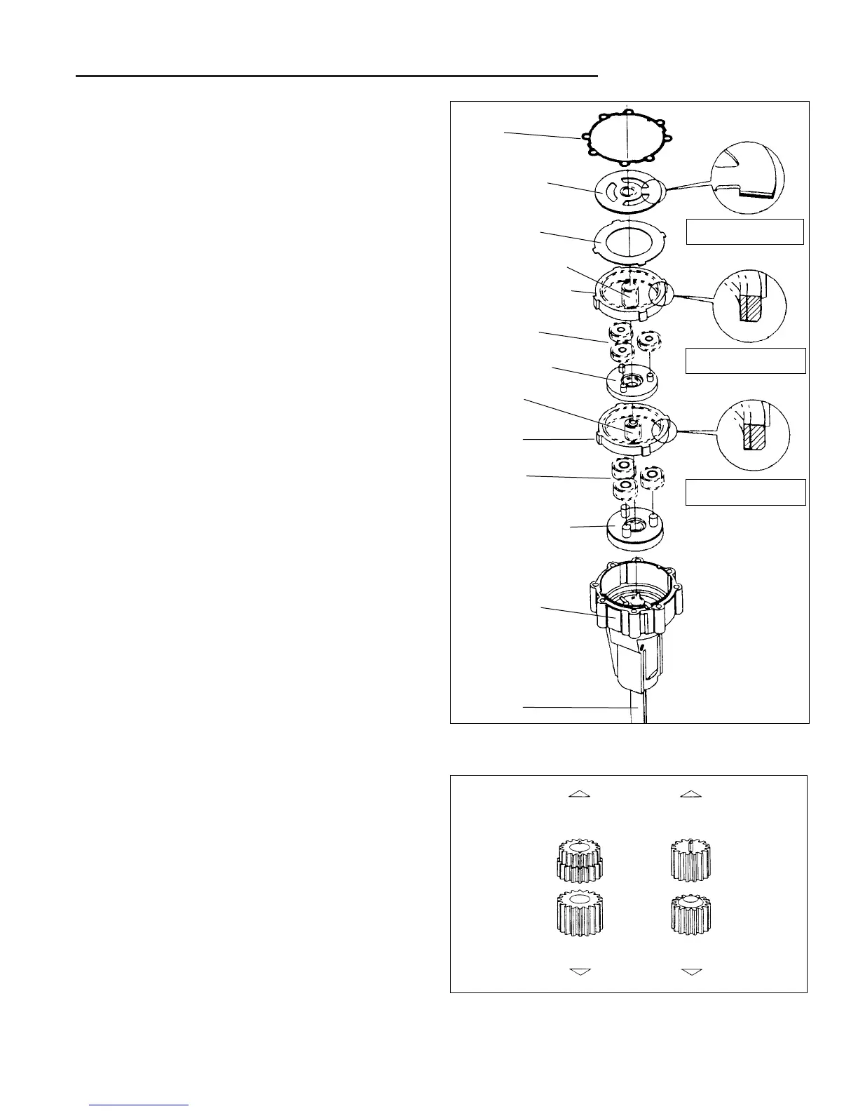
Figure B–98. Assembling Axle
8. Lubricate and assemble the three secondary planet
gears on the secondary carrier.
9. Aligning the splines, install the secondary carrier
assembly on the splined end of the axle shaft located
in the housing assembly.
10. Please note that one side of each ring gear has a
bevel on one side. This bevel side of the ring gear
must be toward the output end of the axle shaft.
11. Install one of the two ring gears into the axle housing.
Install by aligning the ears on the outside of the ring
gear with the notches in the housing assembly.
12. Rotate the secondary planet gears to align with the
secondary ring gear teeth.
NOTE: When ring gear is in alignment, it will drop into
place.
13. Shown here are the first and second sun gears for
16:1 and 23:1 gear ratios.
14.Install the secondary sun gear into the secondary
planetary assembly.
15. Lubricate and assemble the three planetary gears on
the primary carrier assembly.
16. Aligning the splines, install the primary carrier assem-
bly on the secondary sun gear.
17. Install the next ring gear into the axle housing. Install
by aligning the ears on the outside of the ring gear
with the notches in the housing assembly.
NOTE: Rotate the primary carrier assembly and the ring
gear will fall into position.
18. Install the primary sun gear into the primary planetary
assembly.
19.Lubricate and install the backup plate in the axle
housing assembly. Install by aligning the ears with
the notches in the axle housing.
20. Aligning the splines, install the reaction plate on the
primary sun gear (friction material must be toward
backup plate).
21. Aligning the screw holes and notches, install the axle
housing gasket on the axle housing assembly.
Gasket
Reaction Plate
Backup Plate
Primary Sun Gear
Primary
Planet Gears
Primary Carrier
Secondary
Sun Gear
Secondary
Ring Gear
Secondary Carrier
Axle Housing
Secondary
Planet Gears
Axle Shaft
Primary Ring Gear
Friction Material Must Be
Toward Backup Plate
Ring Gear Beveled Edge
Faces Toward Axle Shaft
Ring Gear Beveled Edge
Faces Toward Axle Shaft
Figure B–99. First And Second Sun Gears
16:1 Ratio
Sun Gears
Motor Rotor
23:1 Ratio
Sun Gears
15 Tooth
18 Tooth
18 Tooth
15 Tooth
Output Shaft
Primary
Secondary