NANYTE BEAM Manual
NANYTE BEAM Manual BM-001-A3 / V1.1a Page 32 of 33
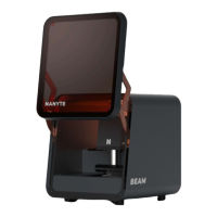
Calibrating the laser beam spot focus offset
It is possible for the laser beam spot to be focused at a level that is different from the sample
surface. This also provides an opportunity to tune for the sidewall profile. Typically, high
resolution features in far field optics will require a large beam cone angle. Thus the beam profile
will look like the one on the leftmost image below. By adjusting the focus level when exposing, it
is possible to slightly alter the sidewall profile to achieve either a overcut or an undercut.
However, it is impossible to know just from using the camera feed; the laser beam spot may look
focused but due to chromatic aberrations, it is slightly different in reality. To find out how which
focus offset can provide the highest resolution, it is necessary to expose, develop, and the
observed from the patterned photoresist.
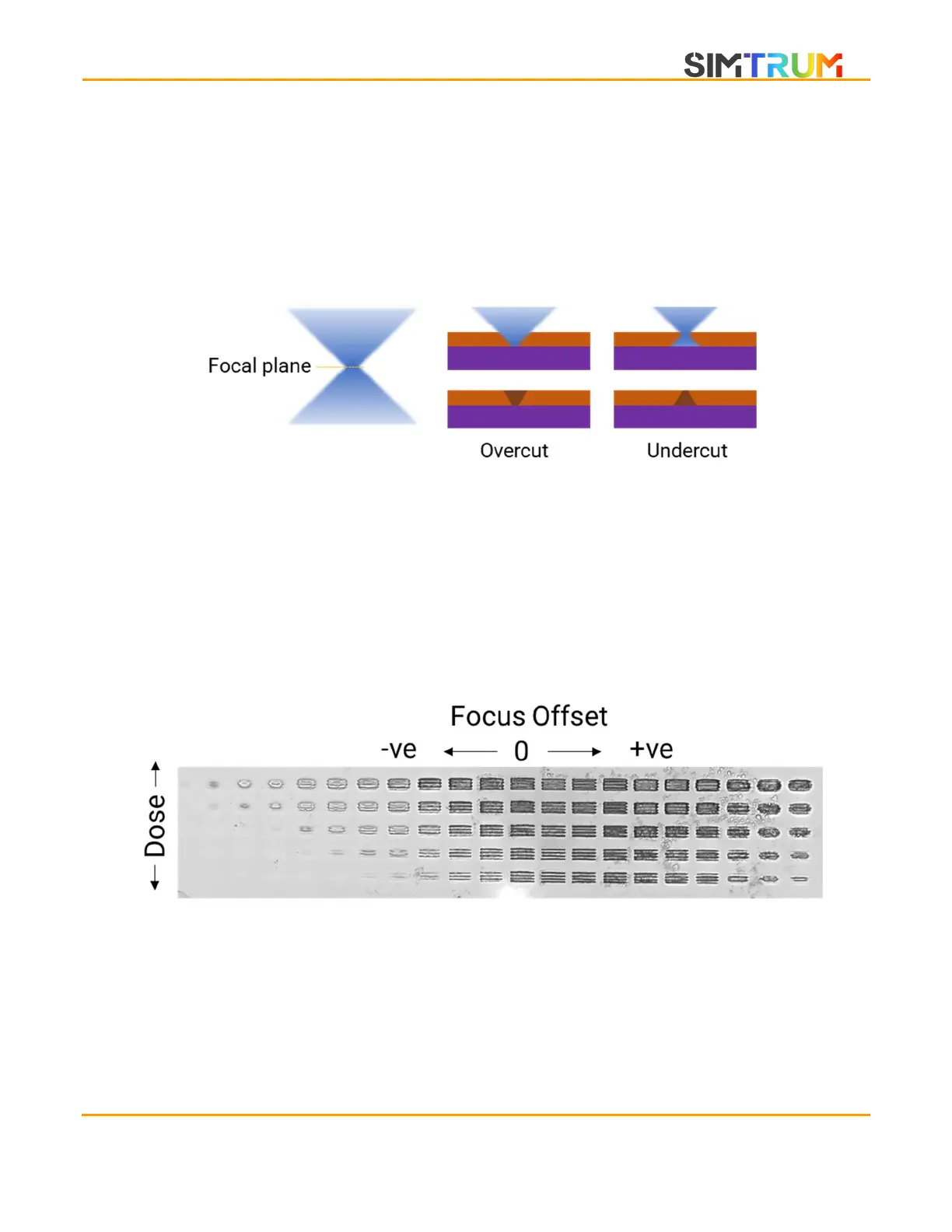
On a resist-coated wafer, find an empty spot and click on Draw Lines. The BEAM ENGINE then
draws groups of 4 lines at a 2 um pitch. The focus is changed from left to right in steps of 3, while
the dose is increased from bottom to top. After development, the resist should form patterns like
the one below.
On the resist patterns, look for the thinnest line that is fully developed. You may wish to use a
high-powered microscope for this purpose. To determine the focus offset, count +3 for each
column that the best lines are from the 0 focus offset. Similarly, -3 for each set of lines to the left.
To choose the best exposure dose, count from the bottom row to the set of best lines in a similar
manner. The dose starts from the start value and increases in steps defined by the step value.
www.simtrum.com