NANYTE BEAM Manual
NANYTE BEAM Manual BM-001-A3 / V1.1a Page 12 of 33
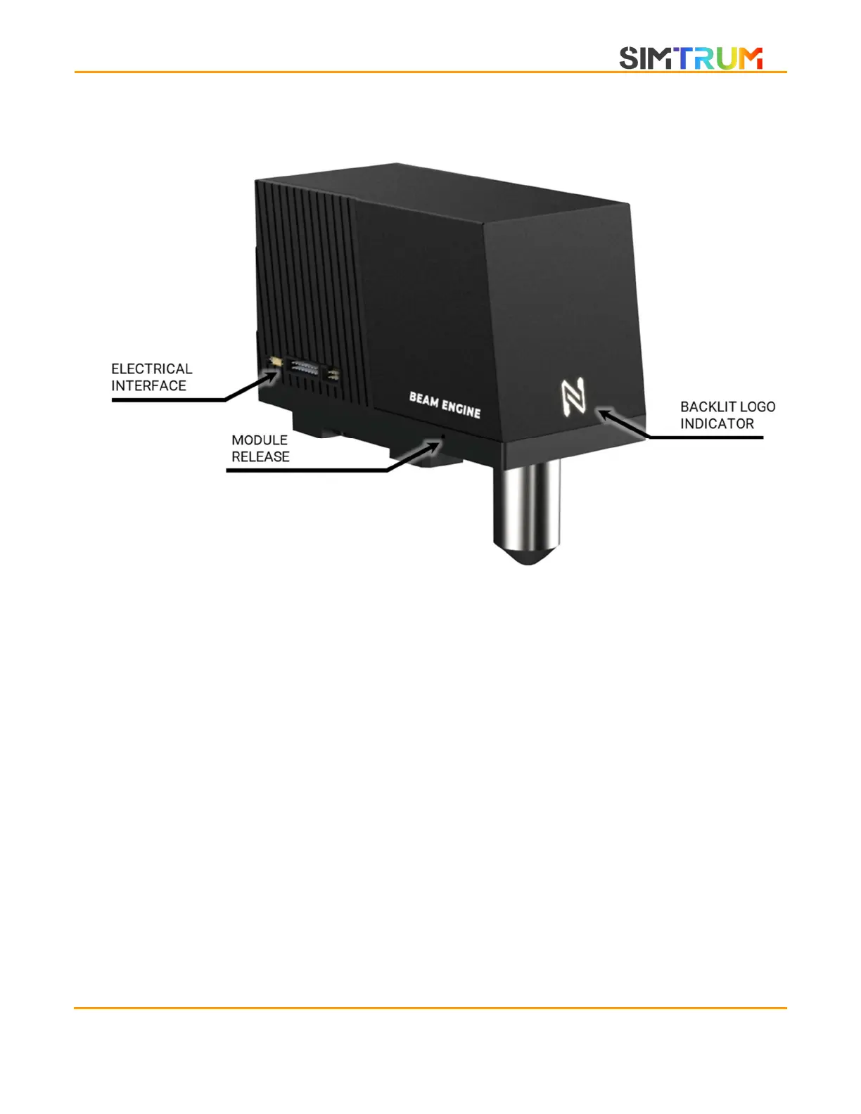
BEAM ENGINE
ELECTRICAL INTERFACE
The electrical interface on the BEAM ENGINE consists of three sets of connections.
1. USB 3.0 Micro connection
2. 16-pin IDC ribbon connection to the motion controller
3. 6-pin IDC ribbon connection to the encoder
BACKLIT LOGO INDICATOR
Provides information about the system status.
1. GREEN – System is powered and ready.
2.
ORANGE – The beam engine is exposing a pattern. The laser is likely to be on.
3. OFF – System power is off.
MODULE RELEASE
There are four module release screws on the same plate. Unscrew with M1.5 allen key to remove
the BEAM ENGINE.
www.simtrum.com