User Manual
EM100 Mini Inverter
18
b. 3-hole Installation
See Overall and Installation Dimensions for the dimensions of 3-hole (Hole b). Refer to
Figure b, and punch 3 holes on the installation panel with screws in each of them. Do not
tighten the screws, leave a distance of 7.5~9mm between the gaskets and installation
panel, hung the inverter onto the 3 screws from top to bottom (Screw size: M4xL,
L>16mm, tightening torque: 1N.m±10%), and then tighten the 2 screws at the bottom.
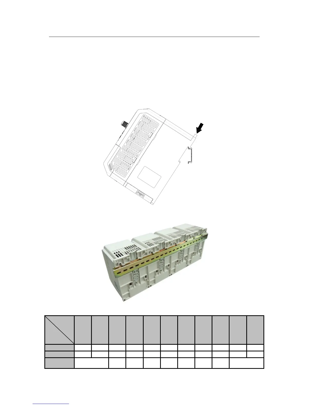
3.1.6 DIN Rail Installation (DIN Rail Width: 35mm)
See Overall and Installation Dimensions for the dimensions of DIN rail. Refer to the
following Figure, install and remove the inverter by pushing the DIN rail release button.
DIN
Rail
Mount multi-inverter in parallel with DIN rail:
3.1.7 Flange Mounting (For the Models with Frame SIZE3&4 )
Unit
(mm)
Frame
W L W1 W2 W3 L1 L2 L3 d H1 H2
SIZE3 138 223 170 157 37 261 249 99 5.5 84 81
SIZE4 156 290 190 177 37 329 317 142 5.5 131 70
Remarks
Size of
mounting hole
Size of depth
 Loading...

