EasyManuals Logo

Sinee EM100-0R7-1B User Manual

Sinee EM100-0R7-1B
120 pages
To Next Page IconTo Next Page
To Previous Page IconTo Previous Page
Page #25 background imageLoading...
Page #25 background image
User Manual
EM100 Mini Inverter
25
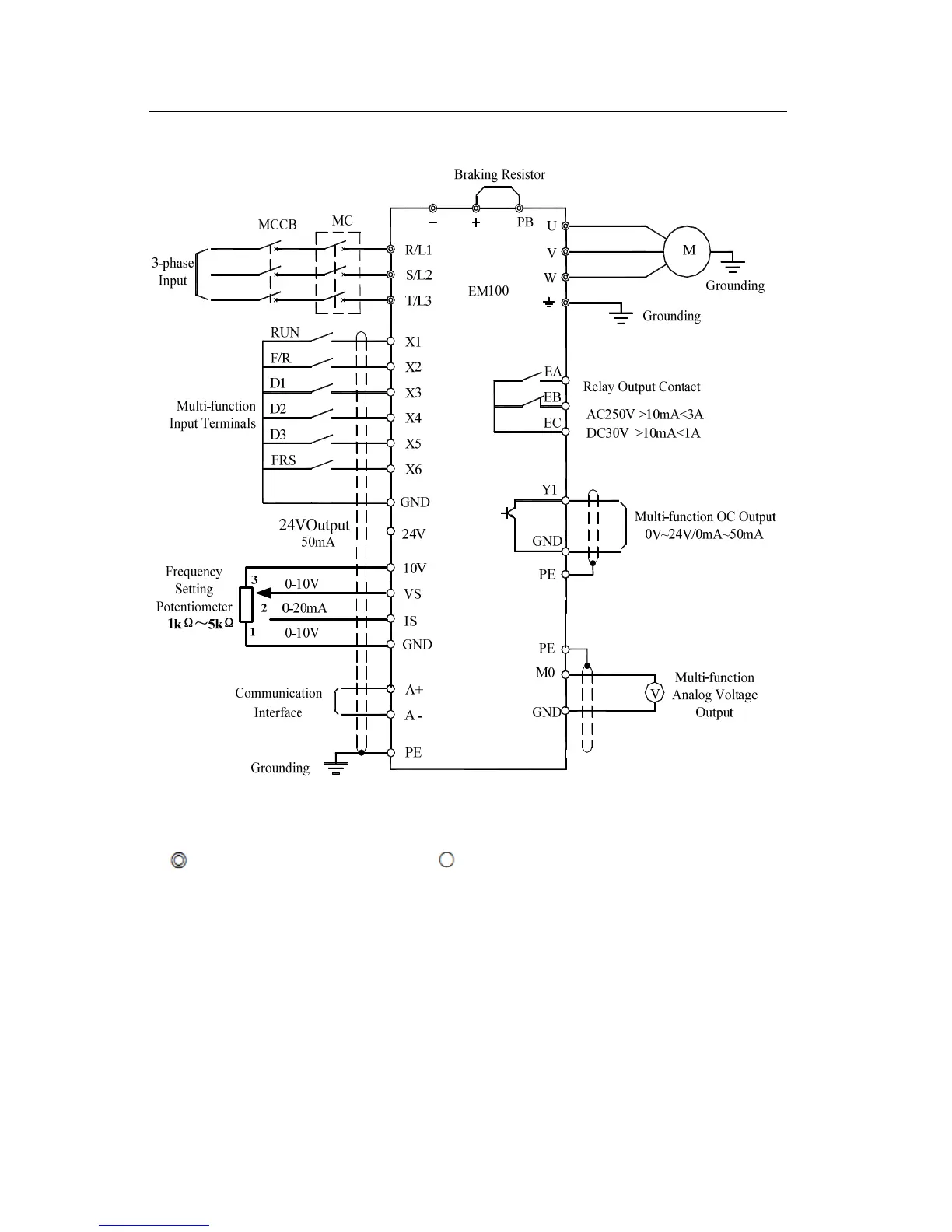
3.2.2 Wiring Main Circuit and Control Circuit
Figure 3-2 Wiring Main Circuit and Control Circuit
Remarks:
1. refers to main circuit terminals. refers to control circuit terminals.
2. User selects braking resistor based on real needs.
3. Signal cable and power cable should be separated. Try to cross control cable and
power cable in 90° if needed.

Table of Contents

Questions and Answers:

Question and Answer IconNeed help?

Do you have a question about the Sinee EM100-0R7-1B and is the answer not in the manual?

Sinee EM100-0R7-1B Specifications

General IconGeneral
BrandSinee
ModelEM100-0R7-1B
CategoryInverter
LanguageEnglish

Related product manuals