User Manual
EM100 Mini Inverter
76
EM100 provides 2 programmable numeric output terminals: 1 multi-function output
terminal and 1 relay output terminal. 0~8 programming codes are available, user can
define the output quantity of output terminals.
0: Inverter is running: When the inverter is running, Y1 or R1 is on.
1: Frequency reach signal (FAR): When the deviation between the output frequency and
setting frequency of inverter in the frequency reaching detection range, Y1 or R1 is on.
Refer to description of F06.06.
2: Frequency range detection (FDT): When output frequency of inverter > FDT increasing
threshold, Y1 or R1 is on. When output frequency of inverter returns the FDT decreasing
threshold, Y1 or R1 is off. Refer to description of F06.07/F06.08.
3: Reverse running: When output frequency of inverter is reversing, Y1 or R1 is on. When
it is forwarding, Y1 or R1 is off.
4: Frequency reached upper limit: When the output frequency reached the upper limit
(F00.12), Y1 or R1 is on.
5: Frequency reached lower limit: When the output frequency reached the lower limit
(F00.13), Y1 or R1 is on.
6: Frequency fault: When inverter is in fault status, Y1 or R1 is on.
7: Inverter is ready to work: When power is on, inverter has no fault, soft-starter runs
normally, Y1 or R1 is on.
8:When the temperature of fan the setting of F07.09, Y1 or R1 is on.
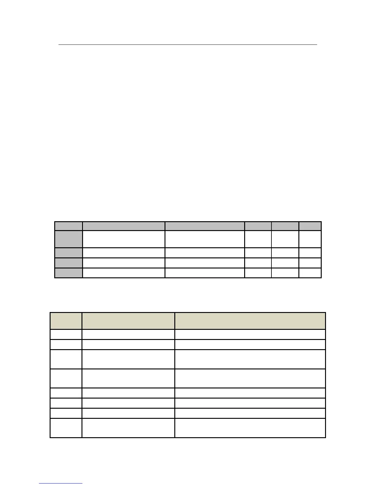
No. Function Range Unit Default Type
F03.02
Analog Output M0
See the Table 6-9 for M0
Programmable Code
0
〇
F03.03
M0 Output Lower Limit
0.00~100.00
% 0.00
F03.04
M0 Output Upper Limit
0.00~100.00
% 100.00
F03.05
M0 Output Gain
0.00~300.00
% 100.00
EM100 provides 1 programmable analog output terminal M0. Analog output terminal
outputs voltage signals (0~10V). See Table 6-9 for the signals and meanings of full scale
corresponding to parameters.
Table 6-9 Programmable M0 Output
Setting
Value
Function Description
0
Output Frequency
0~Fmax corresponding to 0~10V
1
Input Command Frequency
0~Fmax corresponding to 0~10V
2
Output Current
0~2.0 times of inverter rated current
corresponding to 0~10V
3
Output Voltage
0~1.5 times of inverter rated voltage
corresponding to 0~10V
4
VS
0~10V
5
IS
0~10V corresponding to 0~20mA
6
+10V
10V (2mA MAX.)
7
DC Bus
0~1.5 times of inverter rated DC bus voltage
corresponding to 0~10V
 Loading...

